Quick Thing: TARDIS Housing for Raspberry Pi modded for Raspberry Pi 4
This is just a quick note that I updated my Tardis housing for my media center to now hold a Raspberry Pi 4. The new version features:
- An improved “POLICE public call BOX” sign
- A hole for a 5 mm LED in the top for a shining light
- The necessary holes for USB-C, 2x Micro-HDMI and Audio out
- A removable top
The new TARDIS
Here is what it looks like:
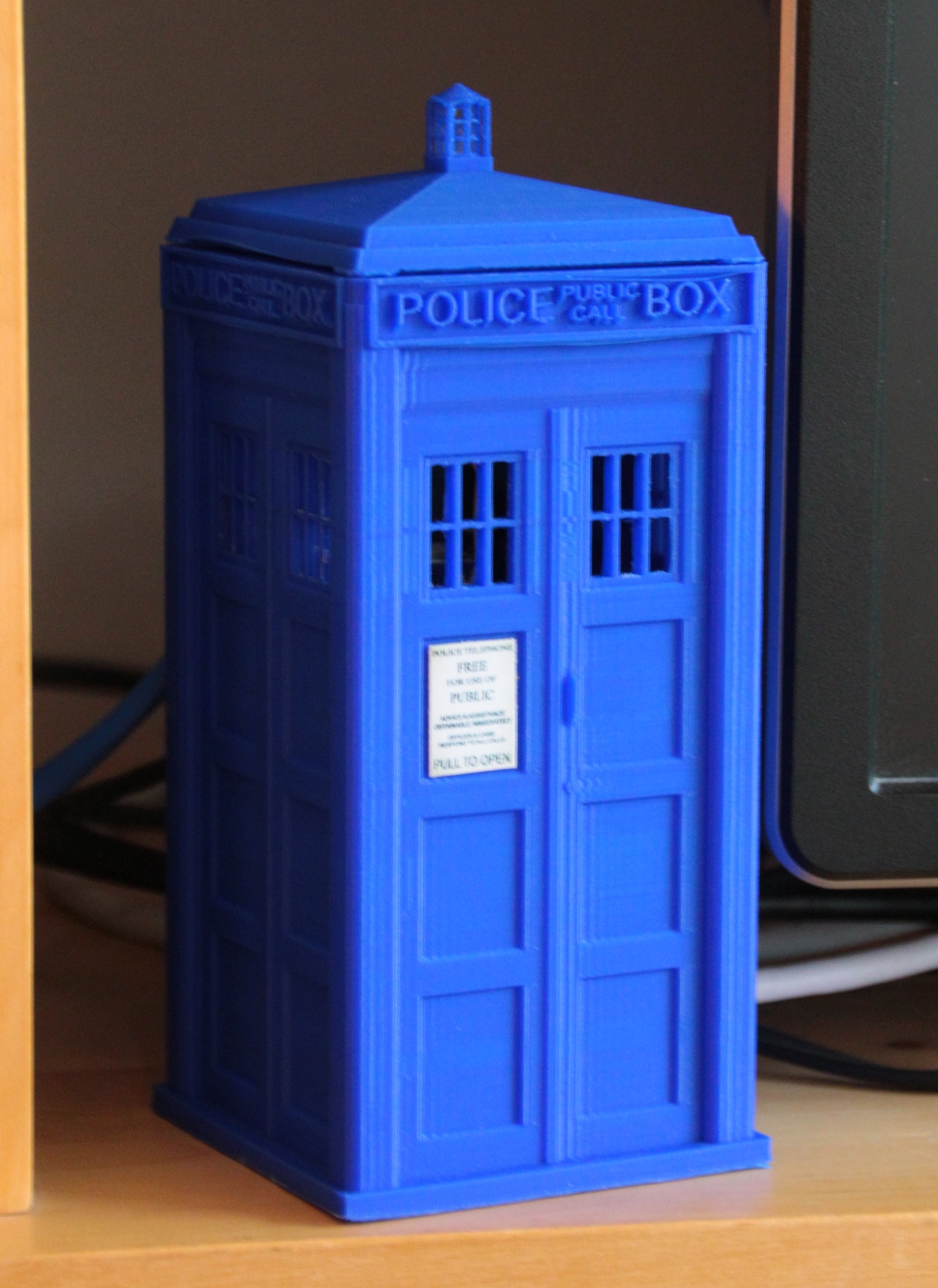
Printed on Fabtotum Personal Fabricator with E3D Lite hotend and Renkforce blue PLA (can’t really recommend this brand…).
The Flashlight
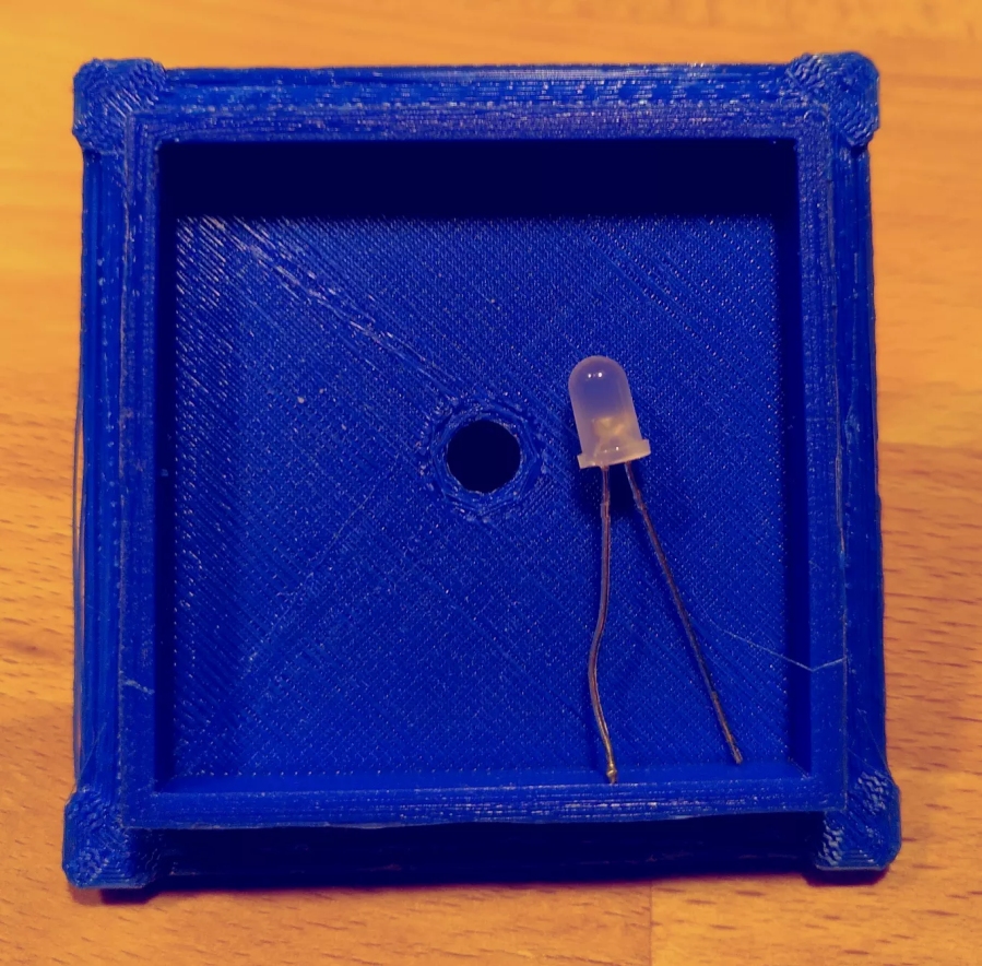
With this incarnation of the TARDIS, I wanted to have a flashlight in the top which once in a while would issue a nice pulsing light. So the model now includes a hole for a 5 mm LED to go into the top light cage:
My media center runs on LibreELEC, so the software part below is targeted for that.
Electronics
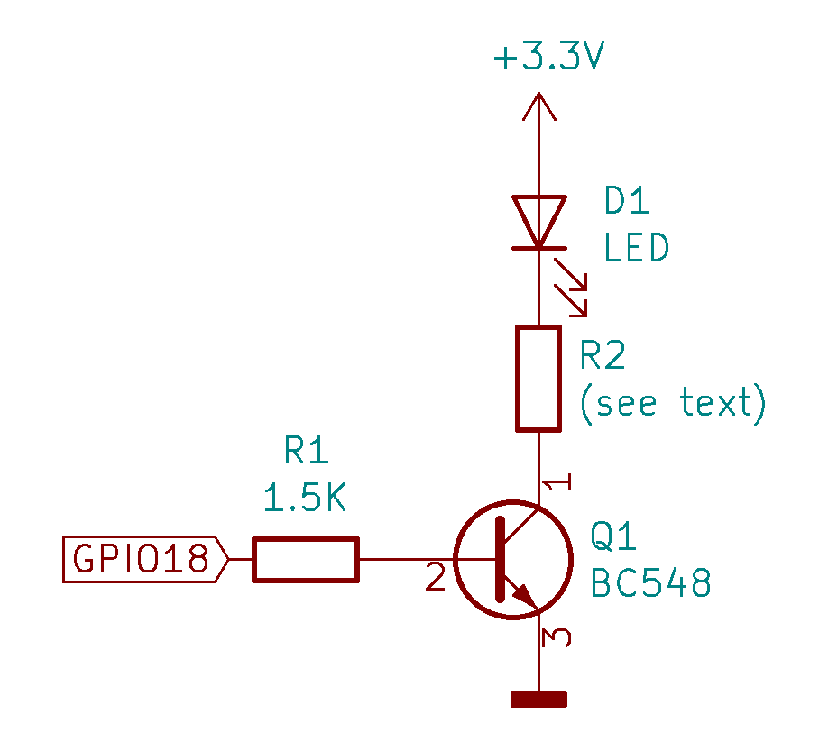
I used a white LED with UF = 3.2 V and IF = 20 mA. Since the Raspberry can only drive 16 mA directly from its GPIO pins, a transistor is needed as driver for safe operation. With the voltage drop across this transistor, a current-limiting resistor R2 for the LED was not required in my case – if you use a different LED, include one matching your LED’s IF/UF. I used GPIO18, since it is capable of hardware PWM – however, since LibreELEC (which I use as media center software) does not offer pigpio daemon, in the end I had to revert to software PWM – works nice enough after all 🙂 Here’s the circuit diagram:
Remarks:
- Any general purpose NPN transistor should be fine
- Value of R1 is not too important, 1 kΩ upwards should be fine, do not exceed perhaps 10 kΩ or so.
- 3.3V are readily available at e.g. pin 1 of the GPIO header
- GPIO18 is pin 12 on the header. Since in the end it’s software PWM, any free GPIO pin should be OK. Just make sure to update code accordingly.
- Nearest GND would be pin 6 or pin 9
Code
First, you need to install the Raspberry Pi Tools addon for LibreELEC, which contains the RPi.GPIO library.
Next, put the following Python script into a directory of your choice (I use /storage/tardislight/tardislight.py):
|
1 2 3 4 5 6 7 8 9 10 11 12 13 14 15 16 17 18 19 20 21 22 23 24 25 26 27 28 29 30 31 32 33 34 35 36 37 |
# From: https://projects.webvoss.de/2020/12/23/quick-thing-tardis-housing-for-raspberry-pi-modded-for-raspberry-pi-4/ # Author: Hauke # Need to add the library path to RPi.GPIO library before import import sys sys.path.append('/storage/.kodi/addons/virtual.rpi-tools/lib') import RPi.GPIO as GPIO import time import random # The higher, the slower (wait time in seconds between each PWM duty cycle increase) Speed = 0.02 # Pin 12 is GPIO18 GPIO.setmode(GPIO.BOARD) GPIO.setup(12, GPIO.OUT) LEDpwm = GPIO.PWM(12, 100) LEDpwm.start(0) # Endless loop while True: for DutyCycle in range(0, 101, 1): LEDpwm.ChangeDutyCycle(DutyCycle) time.sleep(Speed) for DutyCycle in range(100, -1, -1): LEDpwm.ChangeDutyCycle(DutyCycle) time.sleep(Speed) # Adjust here for more/less often flashlight - 900s = 15 min's --> on average one flashlight every 7.5 mins, i.e. 8 per hour time.sleep(random.randrange(900)) # This here will never be reached - just for cleanliness :-) LEDpwm.stop() GPIO.cleanup() |
Modify Speed and random range to your liking. The script as it is will produce one light pulse slowly increasing and then decreasing again, on average every 7.5 minutes, i.e. 8 times per hour.
Finally, create /storage/.config/autostart.sh (or modify the existing one). Include these lines:
|
1 2 3 |
( python /storage/tardislight/tardislight.py ) & |
Reboot LibreELEC, and enjoy 🙂
Result
Here’s a video showing how it looks like:
Make Your Own
Files can be found on Thingiverse or be downloaded here. The top will need support, but make sure not to put support into the LED hole – I guess it will be very difficult to remove.
When I printed mine, I took wrong measurements – the HDMI slots were off by ~1 mm. The files are corrected, but I did not print it again. If you do, would be glad if you’d leave a comment if the holes are now correct.
Merry Christmas everyone!