Soil Water Sensors: Problems with the Ubiquitous DFRobot Capacitative Sensors
Capacitative soil moisture sensors based on this DFRobot-design (and its successors) can be found in numerous blog articles about irrigation automation. For me, they do not work out for two reasons: a) A notable temperature dependency of the measurements, and b) a high failure rate after a few months to a few years. I decided to adopt the concept of my Simple Capacitive Water Sensor for a Water Container for soil moisture measurement, which turns out to work well.
First part is a bit of background – you may skip it and directly jump to the solution.
My Journey so far
The automation of the water distribution in my garden is one of my long-running projects, and a key element certainly is to measure the current state of the soil with enough precision to base the water distribution upon. So how to do it best?
Resistive Sensors: No.
The naïve first approach I jumped to (along with many others on the net) was soil electrical resistance measurement: The wetter, the more conductive. You do not need much: basically two electrodes that go into the soil, a resistor and an A/D converter, which most MCUs readily sport. Very quickly it becomes clear that this does not work well: The electrodes suffer from degradation due to ions emitted and from general corrosion, chemical reactions with other soil components, a change of soil properties by the measurement itself (ions wandering), and changes of the soil conductivity by e.g. fertilizers. First experiments quickly ruled this method out. So next idea you find on the net are
Capacitative Sensors: Yes, but…
The idea behind these sensors: The capacity of a capacitor changes with the electrical properties of the medium between the two plates of the capacitor. Water definitely does change these electrical properties. Only caveat: Measuring capacities is a tad more complex than the simple conductivity measurement above.
The DFRobot Approach: No.
But why develop something yourself when there is a cheap and easy obtainable ready made sensor for this? Enter the DFRobot sensor and its many, many cheap clones and versions. The creator of this approach obviously wanted to keep the A/D converter principle (as with the resistive sensing), and created a circuit that measures the capacity of the soil sensing capacitor, and converts this into an analog voltage, and obviously reasonably well. The basic principle is feeding a constant frequency into a RC low-pass filter, where the C is the soil capacitor, and then do a voltage peak detection. The change in capacity will reflect in a change of the RC filter cutoff frequency, and as a result more or less of the input signal goes into the peak detection circuit. Many bloggers report success with these sensors. So I obtained a few, put them to use and on first glance could confirm: Works! But using these sensors now for a few years, I’m less happy than initially. My problems:
Temperature Dependency
One thing that took me a while to understand was the sensor’s temperature dependency (I only today found this paper that confirms my observation to some extent). The sensors report higher humidity levels when cold as compared to warm or even hot. This does not strike as unusual immediately, because it matches expectations: If the sun burns down on your plot, you expect it to get dry. If night coolness comes in, with it comes dew, and therefore more humidity. But having now an alternative measurement principle (see below), I can see that the effect is artificial, and notable/relevant. My assumption is that the peak detector diode in the sensor’s circuit is the main culprit – these diodes have temperature dependent characteristics.
To quantify this effect: As to my observations, a change of temperature by ~10 °C changes the measurement by 20-30%! That’s not very helpful. And, on top of that, my feeling is that this behaviour is not very linear – at some point the measurement “jumps” up and the soil seems to get wet in minutes out of nothing.
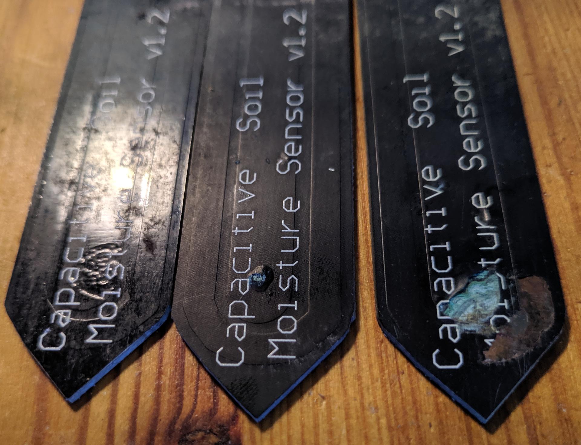
Long Term Stability
The sensor part that goes into the soil is basically a coated PCB. The first batch of sensors I bought had a matte coating, and the first sensor broke after about two years. The second batch I got had a glossy coating, and these sensors last a few months at best. The coating at some point starts to flake off, exposing the underlying copper to soil and humidity. That of course renders proper measurements impossible. I guess sharp stones in the soil scratch the coating, humidity enters and the copper starts to corrode.
So here’s what I ended up with:
Capacitative Measurement by Frequency
The success with my Simple Capacitive Water Sensor for a Water Container encouraged me to try the same principle for soil humidity measurement. Again I used standard power wire (this time brown of course – it’s for soil 🙂 ) as capacitor “plates” material, but unlike with my water barrel, I did not break the copper wire within the insulation, but used two separate pieces of wire and just bent them into U-shape, soldering both ends to the PCB (Watch the video below to see what I mean). I set the two U-shaped “plates” a few centimeters apart to allow a larger amount of soil inbetween as dielectric medium, hopefully getting a more stable measurement, that does not depend so much of how exactly I insert the sensor into the ground. Sampling a larger volume, hopefully would average out “local” effects also.
Using the two 470 kΩ resistors from the original design, in plain water the frequency goes from ~65 kHz (dry) down to ~25 kHz (wet). Looked about right, so I put it into soil. Turns out I might have been better of going a bit lower in frequency, but in the end I have ~100 levels resolution with the used ATMega 328P MCU at internal 8 MHz clock – good enough!
Testing the prototype
The sensor is now out in the wild since more than a year and works well enough. In the beginning I observed short “jumps” in measurements. The solution to this is to collect several measurements as a time series and pick the median value, thereby effectively rejecting outliers. My guess for the reason of the jumpiness is that the copper wires forming the capacitor are excellent antennas, and some external pulsed signal induces a spike. Overall, I find measurements stable, and also not dramatically temperature dependent. I still seem to observe a slight tendency to report more humidity when it gets warmer, but the error in measurement is of the order 2-4% for 10 °C temperature difference, which is tolerable. Still, at some point in the future I’ll investigate this and maybe compensate this in code.
With the NE555 costing ~0.25 €, and the other parts even less, the solution beats even the cheapest DFRobot-clones I could find on Amazon.
In terms of long term stability a bit more patience is needed to give a final verdict, but I do not see what would break the water-tightness of the PVC coated wires. As of now, my sensor goes into the second year, and performs well. It encouraged me to replace all other DFRobot sensors that I still have in use by the same design, only upping the resistor. I’m now introducing one with 1.5 MΩ resistors, and will see how much this influences measurements.
Side Effect: Signal Stability
I did not have any issues with signal quality with my analog sensors (yet?), but the risk is there: If over time the contacts of the jacks show a bit corrosion, resistance of the junctions may change, and this will affect the analog voltages, and thereby the measurements. Measuring frequency is robust against such kind of electrical degradation.
Conclusion
Long-term stable, (near-)non-temperature affected soil humidity measurements can be done very cheap with simple-enough concepts – I will now replace my DFRobot sensor clones with the new concept. The key was the idea to use standard PVC coated power wire for the probing capacitor – I was stuck too much on the idea of using raw PCBs, which I simply could not get watertight. Glad I got the other idea 🙂
Make Your Own
For circuit design and code, please refer to my post Simple Capacitive Water Sensor for a Water Container – I would recommend to replace the 470 KΩ resistors by 1.5 MΩ, or even more, depending on the length of your wires. 1.5 MΩ works good enough with ~12 cm of wire (length measured after being bent into U-shape – so the wire itself is more ~25 cm).
Afterthoughts
Of course the sensors get 3D printed housings, but I dived again into CNC milling my own PCB boards – must say that after getting past a few problems, I finally get decent results with my Snapmaker 2.0. Will perhaps at some point make a post about this. Until then the very short version: Use KiCAD to design your circuit and PCB, then use FlatCAM to create GCode for isolation routing, hole drilling and cutout GCode. You’ll find other tutorials on this aplenty on the web.