CEC-like Power Features with Non-CEC-Equipment
With a Raspberry Pico, I monitor my Sony amplifier from the 90s and my 2013 Dell monitor, and switch on my NUC-based media center if any of these devices are switched on. This is comparable to the CEC functionality that more modern devices provide via the HDMI port. I also utilize the USB/serial interface of the Pico to check if any of the two devices is still on to include this into my auto-shutdown script logic.
As a result, my media center boots up as soon as I switch on my amplifier or my monitor, and only auto-shuts down if both are off.
Click to skip the introductory blah blah.
Motivation
I contradict my claim, that my media center is not really important to me, by already posting the next blog article on it… I admit I got carried away for the fun of it! I guess this is partly because I by now enjoy Spotify quite a lot, and that made it a logical step to bring my venerable Sony TA-F 690 ES into the equation. This high end stereo amplifier from the early 90s has technical spec’s that, even today, put most audio equipment to shame, and it sounds just gorgeous! I mean: Which amp nowadays sports a THD of 0,005%?
The idea was, that if I switch on the amplifier, the NUC boots up without any need to press the power button. Also, I wanted the NUC to stay on as long as the amp is on. While the auto-shutdown script already tests for running audio output and prevents auto-shutdown in that case, it would fail to detect if I paused Spotify, e.g., because I receive a phone call, but plan to continue to listen at a later point. So it might happen that while I’m on the phone, the NUC auto-shuts down. Monitoring the amp’s power-state might prevent this.
Ach ja, first world problems…
And while I’m at it, why not also monitor the monitor 🙂 – if I switch it on, booting the NUC is just logical. For shutdown-control it is already monitored via I²C, but not for power-up.
First Idea
Analysing my options, I identified the following interfaces to make use of:
- An internal CEC header in the NUC (which Intel names external CEC connector…). This provides 5V even if the NUC is off, and via CEC I can boot the NUC.
- On the amplifier the tuner control port, which basically forwards the IR receiver signals to other contemporary Sony devices via a simple 4-pin 2.54 mm pitch connector. Fortunately the signal is inverted, so that with no IR signal present, the level is ~5V if the amplifier is switched on.
- On the Dell monitor a 12V barrel connector output, intended to attach a soundbar to it.
So my original plan was to take an ATtiny85 MCU and make it a CEC client that communicates with the NUC via the CEC interface.
This plan was thwarted by the fact that the CEC interface of the NUC is not exposed to the OS running. Only the NUC BIOS can access the CEC interface. That would be OK if I only wanted to boot the NUC – BIOS would serve its purpose there. But I also intended to use the CEC bus to query the power state of amp and monitor by sending and receiving CEC data packages. That second part was off the table after reading this sentence in the Intel documentation:
The following Intel® NUC Kits have the above external CEC header and an onboard HDMI CEC controller that the BIOS controls. The onboard HDMI CEC controller only supports bidirectional power on/off control.
Whatever I tried, the OS would not identify the CEC controller and expose it via /dev/cec0. Which seems to be that way by design.
Plan B
Well, Plan B it is then. In one of my drawers there slumbered a Raspberry Pico. This 133 MHz dual-core ARM Cortex-M0+ based MCU board is way too powerful for the task at hand, basically it’s pearls before swine, but from an economical perspective it makes total sense. For just 5 € it is simply the cheapest option I could find that has an USB port which I can use for the communication between the OS/auto-shutdown script and the MCU. Even the cheapest Arduino boards with an USB port set you back by 20 bucks…
Implementation
Design Criteria
- Do not modify any of the devices, i.e. use existing ports. No soldering directly to any device, ideally not even have a cable go into any device’s housing.
- Avoid ground loops on the audio side (to avoid humming).
- Low power consumption.
- Play around with optocoupler ICs/isolator ICs. Not strictly necessary, since all devices are galvanically connected via the ground lines of the audio jack and the HDMI cable, but I was curious and wanted to learn.
- Re-implement the Tardis light 🙂
With the Raspberry Pi media center gone, there was no need anymore for the Tardis housing. But I got so used to it… Now the Pico is in the Tardis on top of the NUC, and so the Tardis flashlight of course needed to be back!
The Circuit
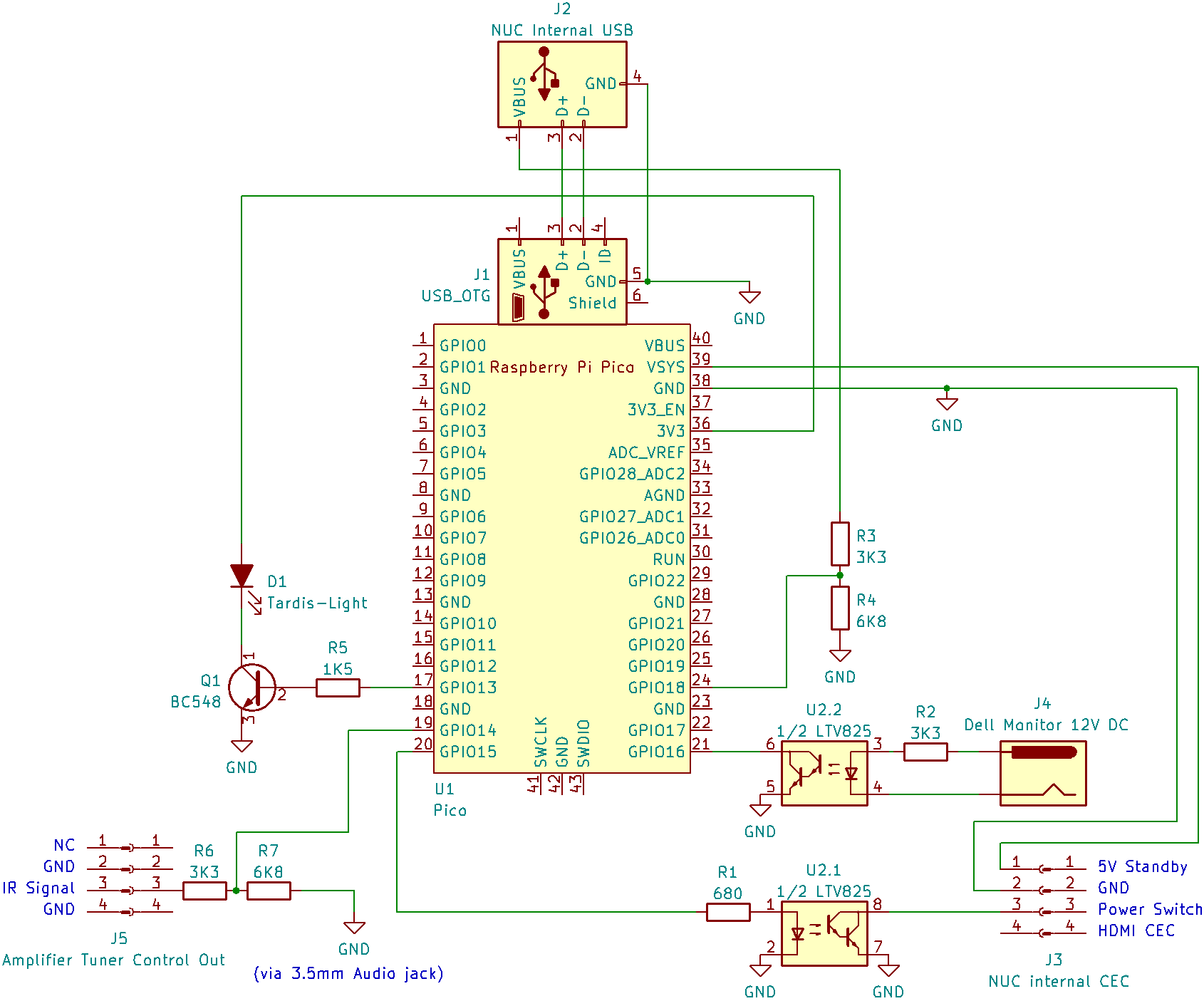
USB Connection: For Communication and Check if the NUC is On
The NUC has two internal USB 2 interfaces, which are 1.25 mm pitch Molex “PicoBlade” connectors. These are really a pain to crimp without the correct tool, but I did not want to buy crimp pincers for just a few connections. I managed with small standard pincers, and also by harvesting an existing cable from an old docking station.
Important: 5V Vbus are not connected to the Raspberry Pico Vbus! This is because I want to power the Pico from the 5V Standby rail, and I wanted to avoid connecting the standby rail to the “hot” 5V rail via the Pico. Still, I use the 5V Vbus from the USB connector for the Pico to check if the NUC is on. Since Pico GPIO uses 3.3V and is not 5V tolerant, with two resistors I created a voltage divider to be compatible.
Monitor 12V Jack
Here I used an isolator IC that pulls down the Pico GPIO if the monitor delivers 12V, i.e. it is on. The isolator IC is not really necessary, I could have used an voltage divider as well. Still, I wanted to try out if I can get it right. The resistor is calculated for less than 4 mA If at 1.2 V Uf. Works like a charm.
Amplifier Tuner Control Out
My multimeter told me that the IR signal pin provides 4.6-4.8 V, but in order to better understand my options, e.g., how much current I could draw, I searched for the service manual for the Sony TA-F 690 ES, which luckily is available as scan on the internet. Here is a condensed version of the circuit plans that shows the relevant parts:
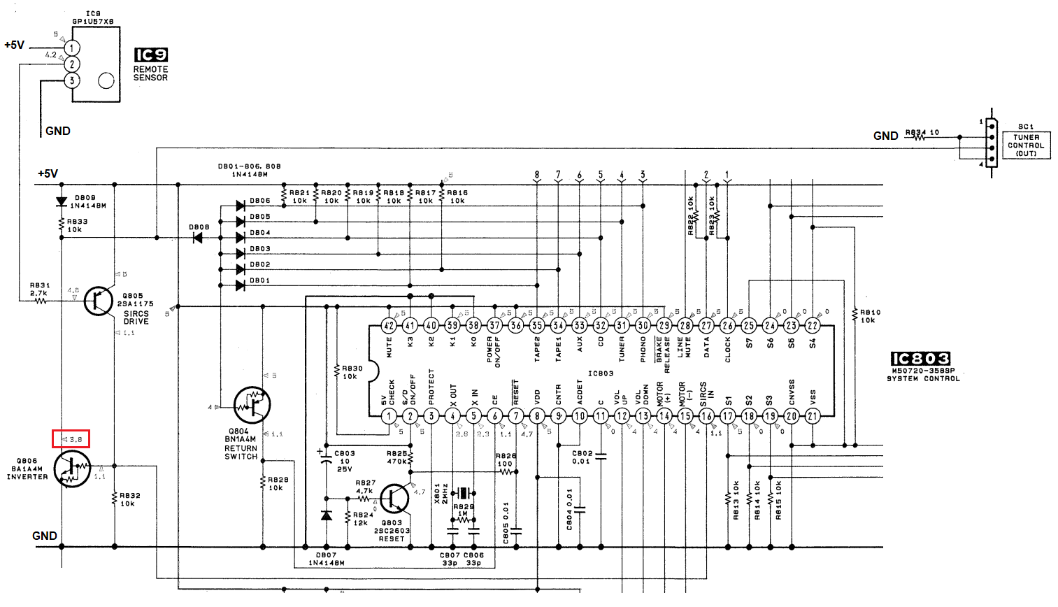
The manual tells me that I should expect something around 3.8 V. From the 1N4148 diode up to 5 V I’d more expect 4.3 V with the 0.7 V voltage drop across a silicon diode. I decided to play it safe and create a voltage divider that assumes ~5 V input, and it works very well.
Only caveat: my oscilloscope showed that ever once in a while some stray IR light triggers the IR receiver, and for a short pulse it pulls down the line. So I’d need to do a bit of debouncing in the code later.
Final remark: I first also connected GND from the tuner port to the Pico GND. This caused nasty humming from a ground loop, since the 3.5 mm audio jack from the NUC to the amp already connects GND. Removed the GND wire from the PICO, and humming gone, functionality still OK.
NUC Power Switch & 5V Standby
The internal CEC header (which Intel calls the external header) provides the power switch pin and 5V standby. It is again a 1.25 mm Molex “PicoBlade” connector. 5V go to VSYS of the Pico and keeps it juiced all the time.
The NUC power switch pin is pulled up to 3.3 V, and Intel documentation tells you that you should pull it down to ground for 50 ms minimum to trigger boot. I decided to do this again via isolator IC, which makes the program logic simple. I can configure the relevant GPIO as output, set it to low, and switch it shortly to high to trigger the power switch. Without the isolator I would have needed to configure the GPIO as input (high impedance), and to trigger the switch I’d have to reconfigure as output and then pull it low to trigger the switch.
The Pico GPIO by default can source 4 mA of current, which you can reconfigure for higher values. The isolator IC I used, the LTV 825, according to the datasheet already goes into saturation at as low as 0.5 mA across the LED, so no need to crank it up. The resistor limits the current to just above 3 mA, and it works fine.
Tardis Flashlight
Simple NPN driver circuit for a white LED, which, using PWM, allows to have the LED going slowly bright and dark again. Read all about it here.
Hardware done.
Software
Raspberry Pico
Setting Up the Arduino IDE
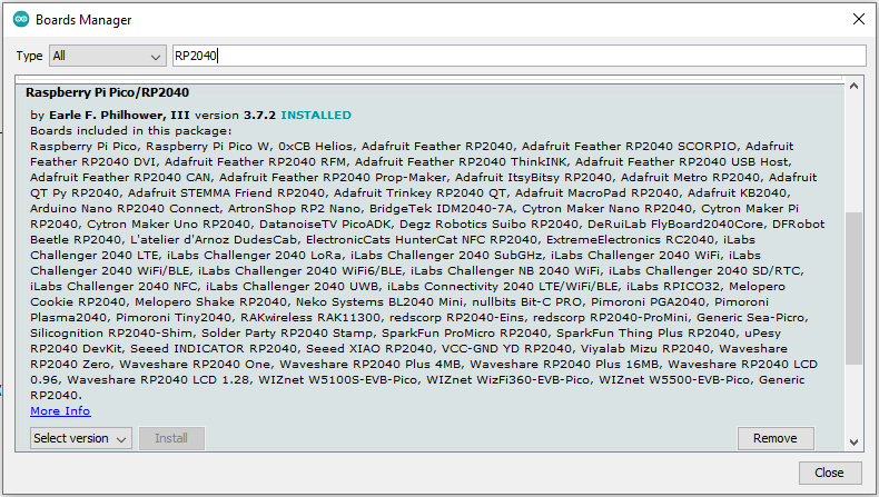
The Pico can be programmed with several tools – since I’m used to the Arduino IDE, I decided to use it here also. There are more than one board library for RP2040 based boards. I went for the library of Earle F. Philhower, III. Thanks for providing that! You need to install the repository as additional board manager URL via the preferences.
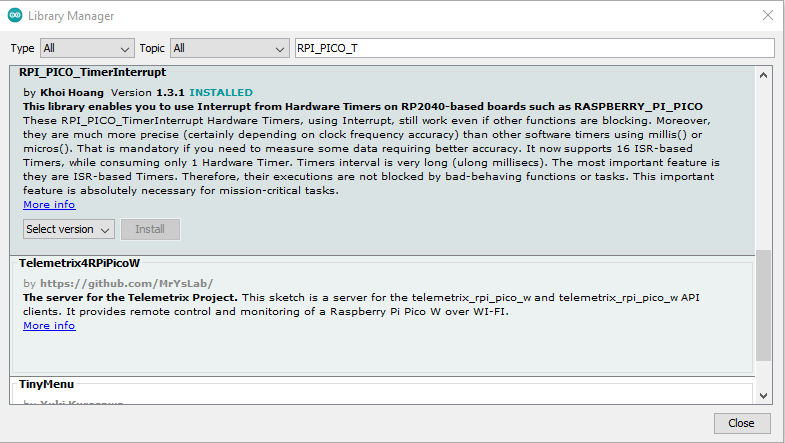
Also, I use the RPi Pico Timer-Interrupt library by Khoi Hoang. Thanks for this library! It comes with the Arduino package and can be directly installed via “Manage Libraries”.
If you have never done the above steps, please refer to the Appendix for a screenshot guide.
The Code
The code is not really complicated. Some key elements:
Flashlight via Timer
For the Tardis light timing I did not want to rely on the standard loop, which – depending on other tasks – may not have always the same execution time, which might cause flickerings in the Tardis light. Instead, using the TimerInterrupt library, I link the function for the LED PWM to a timer. That allows accurate changes to the PWM duty cycle, resulting in a smooth transition from dark to bright and back to dark.
Power State Monitoring and Debouncing
To avoid the NUC to wake up just because the IR receiver got some stray light, I require the change in state to last for at least 1 second. Every ~5 ms the state is measured, and only if it stays changed from the previous state for 200 measurements, it is considered as truly changed. 200 × 5 ms = 1 s.
The green onboard LED of the Pico is used to reflect the current state: If it is on, it tells that amplifier and monitor are off. As soon as one of them is registered as on, the green LED is switched off.
Virtual Button Press
If the power state of amplifier or monitor has indeed changed from off to on, the Pico checks if the NUC is already on – which it knows via the NUC’s USB Vbus. If the NUC is off, the power switch line of the NUC is pulled down for 250 ms, which should be enough to get the NUC booting.
In combination with the debouncing mechanism there’s a second effect: If I actively shut down the NUC, the debounce mechanism avoids that the Pico restarts the NUC immediately in case some periphery is still on.
Serial Communication
For the communication of the auto-shutdown script with the Pico, the USB-based serial interface is used. I kept this very simple: If the Pico receives any kind of input via serial, it will answer “On” if amplifier or monitor are on, and “Off” if none is on. It will then empty the serial input stream buffer, and wait for any new input.
|
1 2 3 4 5 6 7 8 9 10 11 12 13 14 15 16 17 18 19 20 21 22 23 24 25 26 27 28 29 30 31 32 33 34 35 36 37 38 39 40 41 42 43 44 45 46 47 48 49 50 51 52 53 54 55 56 57 58 59 60 61 62 63 64 65 66 67 68 69 70 71 72 73 74 75 76 77 78 79 80 81 82 83 84 85 86 87 88 89 90 91 92 93 94 95 96 97 98 99 100 101 102 103 104 105 106 107 108 109 110 111 112 113 114 115 116 117 118 119 120 121 122 123 124 125 126 127 128 129 130 131 132 133 134 135 136 137 138 |
// Raspberry Pico code to monitor my amplifier and my monitor. If either is on, but the NUC media center is off, // switch it on. Also, have the flashlight of the Tardis wink at random intervals. // // Written by Hauke March 2024. // // https://projects.webvoss.de/2024/03/07/cec-like-power-features-with-non-cec-equipment/ #include "RPi_Pico_TimerInterrupt.h" // Pin assignments #define TardisLEDpin 13 #define AmplifierPin 14 #define MonitorPin 16 #define PC_USBpowerPin 18 #define PowerButtonPin 15 #define PulseInterval 900 // s - an average flash the Tardis light every X seconds #define LEDspeed 8000 // µS - defines the speed of the flashlight going bright and dark again // end setup - variable definitions int Brightness = 0; int Change = 1; unsigned long LastLEDpulse = 0; int NextPulse = 0; bool PulseActive = true; // "true" will cause the flashlight to once pulse on startup int StateDebounceCounter = 0; bool AmplifierOn = false; bool MonitorOn = false; bool PeripheryOn = false; bool PCon = false; bool LastPeripheryState = false; byte SerialFlusher; // LED flashlight is handled by a timer to keep it independent from other tasks RPI_PICO_Timer LEDtimer(0); bool LEDchange(struct repeating_timer *t) { if (PulseActive) { Brightness += Change; if (Brightness == 255) { Change = -1; } else if (Brightness == 0) { Change = 1; LastLEDpulse = millis(); PulseActive = false; NextPulse = random(PulseInterval) * 1000; } analogWrite (TardisLEDpin, Brightness); } else { PulseActive = ((millis() < LastLEDpulse) || ((millis() - LastLEDpulse) > NextPulse)); } return true; } void setup() { // put your setup code here, to run once: pinMode(TardisLEDpin, OUTPUT); // PWM for Taris light digitalWrite (TardisLEDpin, LOW); pinMode (AmplifierPin, INPUT_PULLDOWN); // Pulled up by IR output pinMode (MonitorPin, INPUT_PULLUP); // Pulled down by opto-coupler pinMode (PC_USBpowerPin, INPUT_PULLDOWN); // Pulled up by 5V on USB pinMode (PowerButtonPin, OUTPUT); // Optokoppler LED digitalWrite(PowerButtonPin, LOW); // --> LED off pinMode (LED_BUILTIN, OUTPUT); // green LED on board (GPIO 25) digitalWrite (LED_BUILTIN, HIGH); // --> Acknowledge power on LEDtimer.attachInterruptInterval(LEDspeed, LEDchange); Serial.begin(115200); // while (!Serial); } void loop() { // put your main code here, to run repeatedly: MonitorOn = !digitalRead (MonitorPin); AmplifierOn = digitalRead (AmplifierPin); PeripheryOn = (MonitorOn || AmplifierOn); if (PeripheryOn != LastPeripheryState) { if (StateDebounceCounter < 200) { StateDebounceCounter++; delay (5); } } else { StateDebounceCounter = 0; } if (PeripheryOn && (StateDebounceCounter > 199)) { PCon = digitalRead (PC_USBpowerPin); if (!PCon) { digitalWrite (PowerButtonPin, HIGH); // Virtual PowerPress delay (250); digitalWrite (PowerButtonPin, LOW); delay (1000); // Wait for USB port to get Power } } if ((PeripheryOn != LastPeripheryState) && (StateDebounceCounter > 199)) { digitalWrite (LED_BUILTIN, !PeripheryOn); // Feedback on device detected/not detected - LED on: Devices OFF LastPeripheryState = PeripheryOn; StateDebounceCounter = 0; } if (Serial.available() > 0) { if (PeripheryOn) { Serial.print ("On\n"); } else { Serial.print ("Off\n"); } while (Serial.available() > 0) { SerialFlusher = Serial.read(); } } } |
Auto-Shutdown Script
The auto-shutdown script needs to have serial communication added to query the Pico for the state of the peripheral devices. In theory it should be a simple echo/read sequence with the serial as target, but I could not get it to work reliable:
|
1 2 3 |
stty 115200 -F /dev/ttyACM0 echo "?" > /dev/ttyACM0 read -t1 SerialAnswer < /dev/ttyACM0 |
Somehow the read often did not receive anything, as if the answer was caught before by some other process. Browsing through tons of ideas on the net, I finally ended up with this code:
|
1 2 3 4 5 6 7 8 |
stty 115200 -F /dev/ttyACM0 cat < /dev/ttyACM0 > /tmp/PicoAnswer.txt & CatPID=$! echo "?" > /dev/ttyACM0 sleep 1s kill -9 $CatPID wait $CatPID 2>/dev/null SerialAnswer=$(cat /tmp/PicoAnswer.txt) |
This is far from elegant, but it works reliably. Still, I was so annoyed by this that I shortly considered rewriting the auto-shutdown script in Python…
So here’s the modified auto_shutdown.sh (to understand the idea behind it please read “Media Center Auto Shutdown and RTC Wakeup Based on tvheadend Recording Schedule”) – note that the highlighted lines need to be adjusted for your environment:
|
1 2 3 4 5 6 7 8 9 10 11 12 13 14 15 16 17 18 19 20 21 22 23 24 25 26 27 28 29 30 31 32 33 34 35 36 37 38 39 40 41 42 43 44 45 46 47 48 49 50 51 52 53 54 55 56 57 58 59 60 61 62 63 64 65 66 67 68 69 70 71 72 73 74 75 76 77 78 79 80 81 82 83 84 85 86 87 88 89 90 91 92 93 94 95 96 97 98 99 100 101 102 103 104 105 106 107 108 109 110 111 112 113 114 115 116 117 118 119 120 121 122 123 124 125 126 127 128 129 130 131 132 133 134 135 136 137 138 139 140 141 142 143 144 145 146 147 148 149 150 151 152 153 154 155 156 157 158 159 160 161 162 163 164 165 166 167 168 169 170 171 172 173 174 175 176 177 178 179 180 181 182 183 184 185 186 187 188 189 190 |
#!/bin/bash # This script will shut down the media center PC when idle, and schedule it to wake up via RTC to meet any planned tvheadend recording. # # Conditions for shutdown: # - Blocking file BLOCKFILE does not exist - the files allows to block auto shutdown completely # - Enough time (MIN_UPTIME seconds) has passed since last boot to allow tvheadend to update EPG/Autorec's # - Monitor must be off (i.e. nobody currently actively using the PC) # - No audio is playing (i.e. nobody is listening to Spotify, KODI, web radio etc. with monitor off) # - The raspberry Pico that checks power state of peripheral devises needs to report "Off" # - No recording is in progress currently # - Next planned recording is not in near future (within the next MIN_GAP seconds) # - The previous script run already determined shutdown state, and left the file UPCOMING_SHUTDOWN_FLAGFILE as indicator. # # Wakeup by RTC is scheduled for: # - Next recording time minus PRE_SCHEDULE seconds if recording is planned within the next 24 hours # - In 24 hours if no recording is due earlier - this is to allow tvheadend to get EPG updates and schedule Autorec's # # Logfile of last shutdown check goes into LOGFILE # Logfile that caused shutdown is copied into LASTLOGFILE # Script should be run via cron # # Prerequisites: # - User that runs the script needs passwordless sudo capabilities for commands "poweroff" and "rtcwake" # - ddcutil installed and i2c_dev kernel module loaded # - solaar installed # # V2 by Hauke, Mar 6th 2024, https://projects.webvoss.de/2024/03/07/cec-like-power-features-with-non-cec-equipment/ # Inspired by Mr Rooster in tvheadend forum (https://tvheadend.org/boards/4/topics/27066) ### CONFIG ### # Logfile for last shutdown check LOGFILE="/home/the-user/autoshutdown/shutdown_check.log" # Logfile of run that caused last shutdown LASTLOGFILE="/home/the-user/autoshutdown/last_autoshutdown.log" # Blocking file to avoid shutdown process completely BLOCKFILE="/home/the-user/autoshutdown/no-shutdown.flag" # If the script identifies that the system should shut down, it will not do immediatly. It will first # create this file. Only if this file exists, the actual shutdown will happen. This will make sure that at least # once the script running interval will pass before a shutdown happens. The file will be deleted if the reason for # shutdown does no longer exist on second run, and no shutdown will happen in that case. UPCOMING_SHUTDOWN_FLAGFILE="/home/the-user/autoshutdown/upcoming-shutdown.flag" # Number of seconds the system needs to be up before a shutdown will happen (to allow tvheadend to scan EPG and update autorecs) MIN_UPTIME=1800 # Minimum time in seconds until next recording for processing shutdown - if gap is smaller, no shutdown , but wait for recording MIN_GAP=1800 # Seconds to boot before scheduled recording time PRE_SCHEDULE=120 ### END CONFIG ### echo "Auto-Shutdown check starts... ($(date))" > $LOGFILE if [ -f "$BLOCKFILE" ]; then echo "Blocking file $BLOCKFILE found - will not process shutdown!" >> $LOGFILE rm $UPCOMING_SHUTDOWN_FLAGFILE 2> /dev/null else # Get uptime in minutes on_time=`date --date="$(uptime -s)" +%s` up_since=$((`date +%s`-$on_time)) if [ $up_since -gt $MIN_UPTIME ]; then ## Only restart if the system was up for at least 30 minutes to give tvheadend enough time for EPG update and autorec update # Get status of monitor: is it switched on? 0 = monitor is on ddcutil detect 2> /dev/null | grep -q 'Display 1' monitor_off=$? if [ $monitor_off != 0 ]; then # If monitor is on (= 0), assume someone is using the computer and do not shut down # Check if any audio output is going on (assume that music is playing with monitor off --> do not shut down) # 0 = some audio playing pacmd list-sink-inputs | grep -q "state: RUNNING" no_audio_playing=$? if [ $no_audio_playing != 0 ]; then # Only shut down if no audio is playing (else assume someone listens to music with monitor off) # Query Raspberry Pico via serial interface. Will report back "On" if any relevant peripheral devices # (Amplifier, monitor) are currently switched on, in which case the PC should keep running. stty 115200 -F /dev/ttyACM0 cat < /dev/ttyACM0 > /tmp/PicoAnswer.txt & CatPID=$! echo "?" > /dev/ttyACM0 sleep 1s kill -9 $CatPID wait $CatPID 2>/dev/null SerialAnswer=$(cat /tmp/PicoAnswer.txt) if [[ $SerialAnswer != "On" ]]; then # Either no response or "Off" from Raspberry Pico --> can continue with shutdown # Check if the wireless keyboard is connected. Unfortunately keyboard at sleep yields same result... solaar show | grep -q "device is offline" keyboard_off=$? if [ $keyboard_off -eq 0 ]; then # only shut down if keyboard is not connected (if it is connected, assume user is active) # Check for active recordings curl -s "http://localhost:9981/api/dvr/entry/grid_upcoming?limit=99999" -u "tvheadenduser:password" --digest | grep -q '"sched_status":"recording",' no_record=$? if [ $no_record != 0 ]; then # Not recording, can we shutdown? if [ -f "$UPCOMING_SHUTDOWN_FLAGFILE" ]; then # Check if at last script run shutdown condition existed - only then shut down. next_recording=`curl -s "http://localhost:9981/api/dvr/entry/grid_upcoming?limit=99999" -u "tvheadenduser:password" --digest | tr , '\n' | grep start_real | sed "s/.*start_real.:\([0-9]*\).*/\1/" | sort -n | head -1` # If there are no recordings we should wake up tomorrow if [ "$next_recording" = "" ]; then echo "No recordings, wake up tomorrow." >> $LOGFILE next_recording=`date --date "tomorrow" +%s` else echo Next recording: `date --date="@$next_recording"` >> $LOGFILE fi gap=$(($next_recording-`date +%s`)) if [ $gap -gt $MIN_GAP ]; then # The gap to the next recording is more than minimum gap, so lets shutdown if [ $gap -gt 86400 ]; then # Wake up at least once a day to update EPG and identify new autorecordings echo "Next recording more than one day in the future - wake up tomorrow." >> $LOGFILE next_recording=`date --date "tomorrow" +%s` fi # Set the wakeup before the next recording according to pre-schedule config wakeup=$((next_recording-PRE_SCHEDULE)) wakeup_date=`date --date="@$wakeup"` echo "Waking up at: $wakeup_date" >> $LOGFILE # Program RTC /usr/bin/sudo /usr/sbin/rtcwake -m no -t $wakeup >> $LOGFILE # Save current logile for review after reboot cp $LOGFILE $LASTLOGFILE # remove flag file, no longer needed rm $UPCOMING_SHUTDOWN_FLAGFILE 2> /dev/null # ...and shutdown. /usr/bin/sudo /sbin/poweroff fi else # First time shutdown reason was detected - do not shut down, set flag for next script run echo "Would shut down, but will wait for another cycle." >> $LOGFILE touch $UPCOMING_SHUTDOWN_FLAGFILE fi else echo "Still recording. Not shutting down." >> $LOGFILE rm $UPCOMING_SHUTDOWN_FLAGFILE 2> /dev/null fi else echo "Wireless keyboard connected, no shutdown." >> $LOGFILE rm $UPCOMING_SHUTDOWN_FLAGFILE 2> /dev/null fi else echo "Raspberry Pico reports active periphery, no shutdown." >> $LOGFILE rm $UPCOMING_SHUTDOWN_FLAGFILE 2> /dev/null fi else echo "Audio is playing, no shutdown." >> $LOGFILE rm $UPCOMING_SHUTDOWN_FLAGFILE 2> /dev/null fi else echo "Monitor is on, will not shut down." >> $LOGFILE rm $UPCOMING_SHUTDOWN_FLAGFILE 2> /dev/null fi else echo "System is up less than $(($MIN_UPTIME/60)) minutes - no shutdown." >> $LOGFILE rm $UPCOMING_SHUTDOWN_FLAGFILE 2> /dev/null fi fi |
Configuration
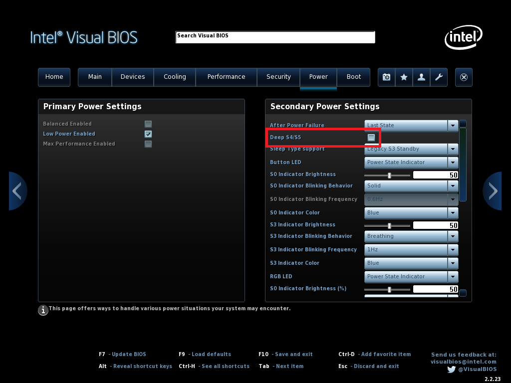
When I first tried the setup, I was in for a bad surprise: The Pico did not stay on when the NUC went into S5 power state (i.e. as off as it can be with external power still on). Turns out that only the 3.3V standby power rail is powered in S5. As much as I would have liked to use the 3.3 V standby voltage, it is not exposed to any header. Fortunately, the 5V standby power can be activated via BIOS – you need to deactivate the “Deep S4/S5” feature:
This will certainly raise the S5-power consumption of the NUC. When I can lay my hands on a power meter, I’ll check the numbers.
Housing
It would have been possible to squeeze the Raspberry Pico somehow into the NUC itself, but as already indicated earlier, I really like my Tardis housing that I used for the Raspberry Pi based media center incarnation. Now I wanted to have the Tardis sitting on top of the NUC, and the cables that go into the NUC (slightly deviating from the design principles) to run through the cover.
Intel does a cool thing: They publish their design files for the NUC covers! (Edit: It seems that only recently Intel removed the relevant files from their pages, since Asus has taken over the NUC brand/support. I yet did not find the lid files published by Asus, but due to copyright reasons I am reluctant to publish the previously downloaded file here on my blog. At the time of this writing, the direct link to the ZIP file at Intel’s pages still worked.) So based on that I was able to design my own NUC cover:

I decided to make the bumps of the noses, that click into the NUC base, considerably thinner. I was afraid that they’d break off from the mechanical strain, as the 3D printing layer structure would be weak in that direction. Turns out I was right: the smaller noses all broke off very quickly – so consider to remove them before 3D printing. The larger ones are OK. Or do a resin print, might be the better choice here if you have that option.
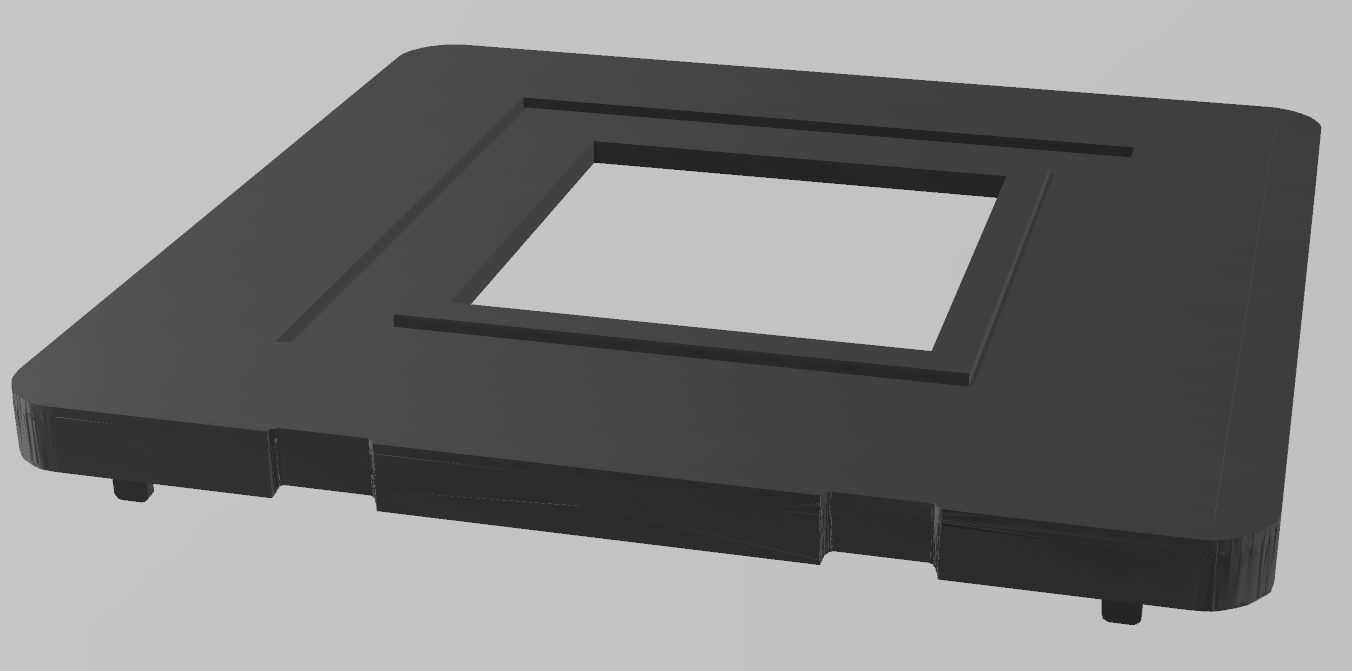
You can see the recess where the Tardis sits in.
And here’s how it looks in reality:
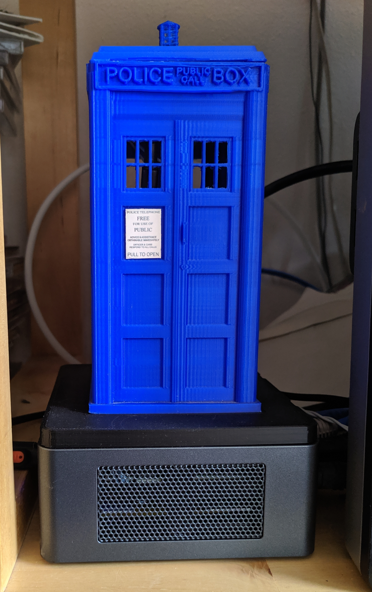
This is now in place since a few weeks, and I’m quite happy how it performs! The only “problem” I identified: If I just want to listen to a CD, the media center not involved at all, it switches on due to the amplifier switched on. Since there are so many unused GPIO pins on the Pico, I may consider including the CD player power state to be monitored, and have the NUC only boot if amp is on but CD player is off… back to first world problems…
Appendix: Setting Up the Arduino IDE
Installing the Board Manager
To install the Raspberry Pico board manager library, open the Arduino Preferences:
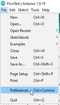
Then, click on the edit icon right of the “Additional Boards Manager URLs”:
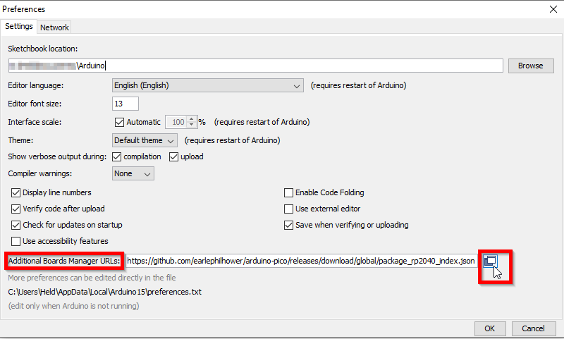
Then add to the list the JSON-URL from the library github:
https://github.com/earlephilhower/arduino-pico/releases/download/global/package_rp2040_index.json
Confirm your modifications and open the Boards Manager:
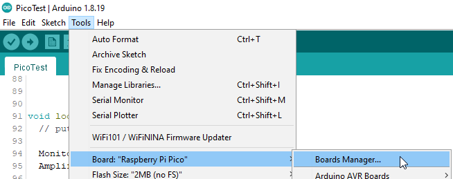
Now locate the board library and install it:
You can now select the Raspberry Pico from the regarding list:
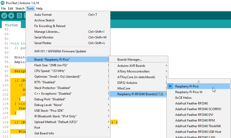
The default settings were just right for me.
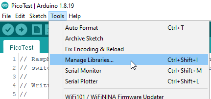
Installing the TimerInterrupt Library
The library is already part of the “stock” libraries that come with the IDE, but you still have to install it. Just open the Library manager:
Locate the correct library and select install:
Now you’re set up to compile my code.