Modified Housing for Alber e-motion M25 Remote Control
For a relative that’s paraplegic, I modified the housing of the remote control for the electric wheelchair wheels Alber e-motion M25 to make the usage easier. Mainly, the small housing was made thicker and larger for better handling. Also, one knob was moved to a different position.
The project is not very sophisticated, but I publish it anyhow – perhaps some other handicapped person can benefit from it.
Motivation
One of my relatives is paraplegic after an idiot, driving tired and falling asleep, crashed into her car. <Rant>He was an idiot doubly so, since at his side was his wife, not tired and perfectly fit to drive, but obviously he insisted on driving himself. Oh, did I say he’s an idiot?</Rant> Since then, she is sitting in a wheelchair, and has motors in the wheels to support her moving around. Recently, her old Alber e-motion M15 wheels gave up the ghost and where replaced by the newer model M25. Both models are controlled with a remote control, but the RC device has significantly changed between the models. My relative is rather unhappy, because with the restrictions the accident inflicted on her, the new, rather tiny RC was difficult to handle. The criticism was:
- Keys too small
- Keys too close to each other
- RC too small to hold reliably in her handicapped hands
- Bluetooth connection slow to start and not robust with other Bluetooth devices closeby
We contacted Alber, but they said: sorry, we cannot do different models for the RC, the numbers we sell don’t justify this. And sorry, you can’t have the Bluetooth protocols to create your own remote, they are to be protected as a security measure. I yet did not put pressure behind it – I guess, the latter argument is just self-protection. But they suggested: If you are technically versatile – why not alter the original RC? After all, not too bad an idea, so I went to work. Of course I cannot do anything about the stupid Bluetooth approach, but the other points I could address. So together with my relative we decided upon the target dimensions of the new RC and about key positions. The key size, if keys are seperated well, would be OK, and we kept it. Here’s the final outcome (she wanted it red…) as a teaser 🙂

Realization
The following things needed to be done:
- Design the new bottom part, the cover extension and the cover part for the moved knob – I did so using 3D Builder
- Print it
- Cut the new hole for the knob
- Do the electric parts for the new knob position and the battery holder (The old battery holder is in the bottom part of the RC, which I replace by my new bottom)
- Assemble everything
Designing the Parts
The following image shows the various parts. These are top to bottom, then left to right:
- The original PCB – you can see the contact pads for the knobs
- The battery cover and
- The new bottom RC part with
- six screw holes matching the original RC cover
- two holes for the backside knobs for reset and pairing
- four pads to hold the PCB in place
- one large pad to hold the new contacts for the moved knob
- the battery holder with contacts (spring and plate) harvested from a broken walkman
- four screw holes to hold the top cover extension
- a slot to put a thread through to attach the RC to the wheelchair
- a place to put a nut into to match the fixing screw of the battery cover
- The two backside knobs (unaltered)
- The cover for the no longer used old knob position (misprint for illustration – the correct cover is already in place in the original RC cover)
- A cutout from an old TV RC PCB to serve as new contacts for the moved knob
- The power knob (unaltered)
- The original RC cover (new hole drilled into and inserted knob hole cover)
- The covor extension to match the longer bottom
- The two knobs, which are cut in the middle so that the left part can be moved down
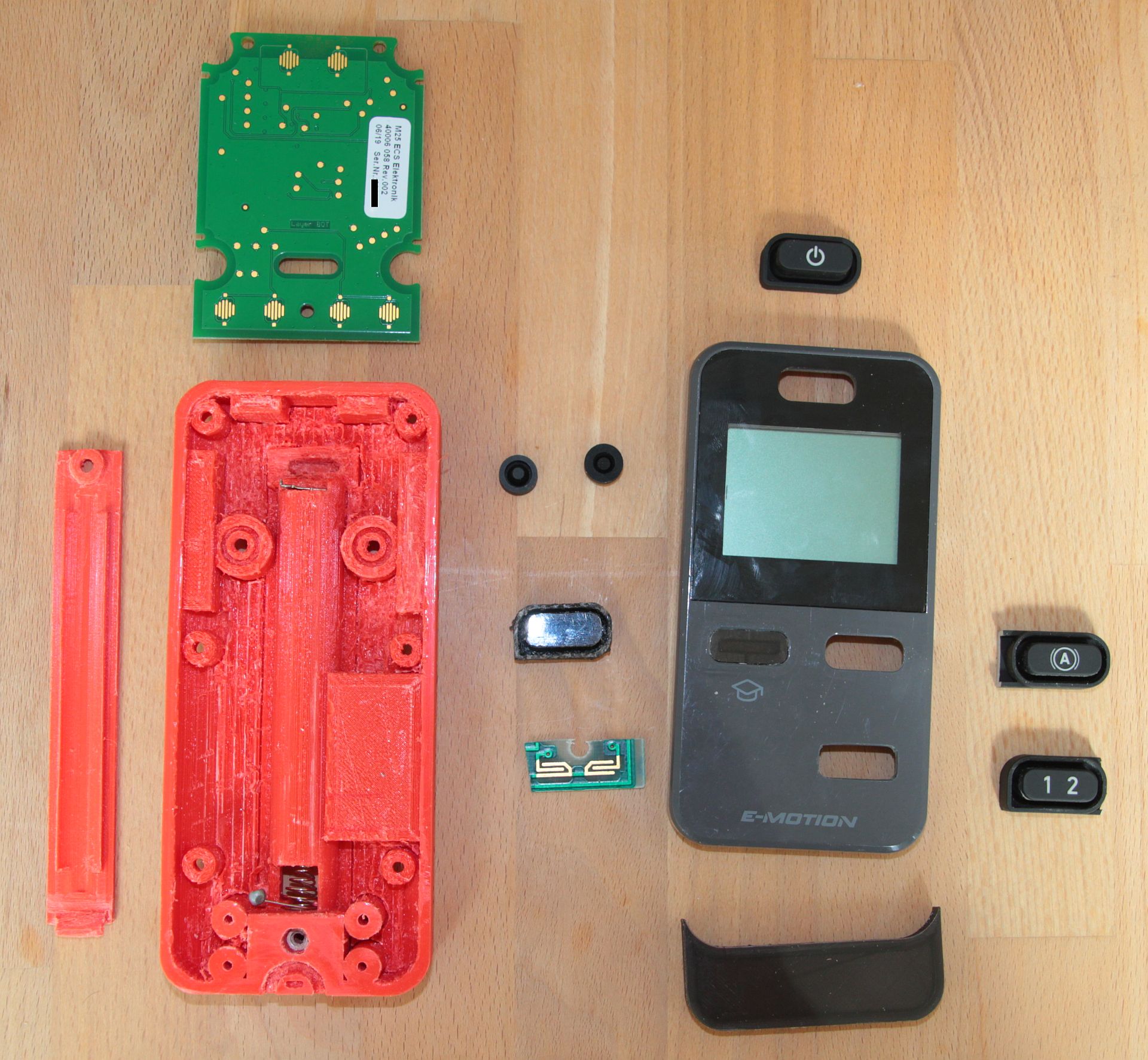
The bottom part was straightforward, but still a lot of work, having several holes, a battery holder and pads to hold the PCB parts in position. The large pad middle-right is to carry the PCB cut from an old TV RC. The TV RC contacts match the contact pads of the moved knobs very well! If you build your own, you may need to adjust the battery holder contact slots, since you may have different parts there. Mine are from a broken, cheapo walkman, just a plate for +, and a spring for -.
The battery cover also was not too much of a hassle. If I would do it again, I might add some stabilisation: The one you see tends to bend a bit.
The cover for the no longer used knob hole needed a bit of precision, so the first print came out a bit to small.
The cover extension again was nothing very difficult.
Everything needed some precision, since the original parts that I kept set the scene. The original top cover I needed to keep, since the display is fixed into it and cannot be removed.
Printing
I printed the knob hole cover and the cover extension directly on glass to have a shiny surface that matches the surface of the original cover.
The bottom part I printed upside down to a) have a smooth matching border to connect seamlessly to the original part, and b) have some protuding parts nice and clean on the later bottom side. The drawback is that a lot of support needed to be printed on the inside, which in the end I was not able to remove completely. The inside looks a bit ugly in places, but this is hidden in the end, so nobody cares. I decided to print thick walls (2 mm) to have them mechanically robust. The RC may drop at times to hard ground, and I wanted the parts to survive such a drop.
The battery cover has no challenges when printing.
Cut the New Hole (Optional)
You of course only need this step if you also need to move the knob. If you are happy with the knobs, this can be omitted.
My girlfriend assisted me here, being a goldsmith she is used to such fiddly work. She used a handheld spindle with drills and sanding tools. Aside from the obvious hole, you need to carve a recess that matches the bulge that surrounds the knob. I forgot to take a photo, but you’ll see what I mean if you have your RC unassembled in hand.
The two knobs for power choice and brake behaviour are one piece of rubber, so I needed to cut them in the middle.
Electric Parts
Battery Holder
After inserting the contact plate and spring, I soldered wires from the contacts to the PCB socket of the old battery holder. I could not get a matching plug, and I did not want to cut the original one, so I directly soldered the wires to the PCB. Watch polarity, as far as I could understand the circuit, there is no protection against wrong polarity!
Knob Contacts
Putting the original cover in place, I adjusted the position of the TV RC cutout to be right under the new hole. There I fixated it with a generous amount of superglue. I suppose that should be stable enough, and as of now, the RC being in use a few months now, it’s fine. You need to figure out where to solder the wires to, and I also had to connect a few conducting paths, but this is easy to figure out. On the original PCB close to the contacs for the knobs there are squared test points (see photo above) to which I soldered the other end of the wire. I used thin, enamelled wire.
Assembly
I think it is rather obvious what goes where. Only remarkable things:
- I used the original screws to attach the original top cover
- I used M 2.5 screws to hold the top cover extension in place – no nuts on the other side, just screwed directly into the plastic (be careful not to overtighten!)
- I used a M 3 screw and matching nut for battery cover fixation
- At some places I put rubber to improve water tightness, although I do not think I achieved the same sealing as the original RC.
When everything was put together, I was happy to see that it still worked:
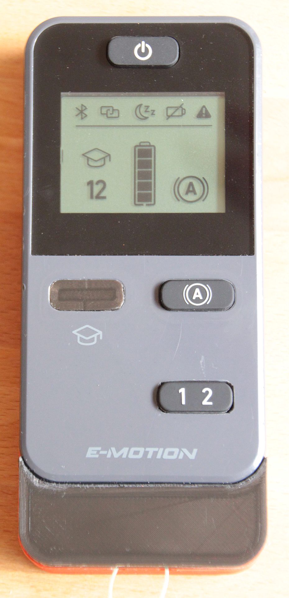
The new RC is in use now since a few months, and my relative is happy(er) with it.
Make Your Own
You can download the 3D files here or from Thingiverse. If you need to modify the models and hit a limit, please get in contact with me, I can provide intermediate steps you may use, but which need a bit of explanation.
If you keep the knobs in the original position, you of course need not print the knob hole cover, and you can remove the large pad from the bottom part.