Case for MP1584 Based Step-Down Converter Board with USB Port
This post is to share my self-made 3D printed housing for a 5V USB voltage converter. Since the used converter board is quite common, I guess others may profit from this design.
Motivation
I use an old laptop PSU with 19.5 V to power two Raspberry Pis via Ethernet cable (kind-of passive PoE using simple injectors from Adafruit). I use these cheap MP1584 based adjustable step down converters to convert the 19.5 V down to 5 V for the Raspberry. The advantage is that I need not care about voltage drop across the cable, which would have been a problem if I would feed 5 V directly into the injector. Now I wanted to put a third Raspberry with an attached 2.5″ hard disk in an USB powered SATA-to-USB case just beside the PSU, so the injector would have been just a waste of money. I salvaged a USB port from an old computer housing and created a 3D print case for the converter board and the USB jack.
Design
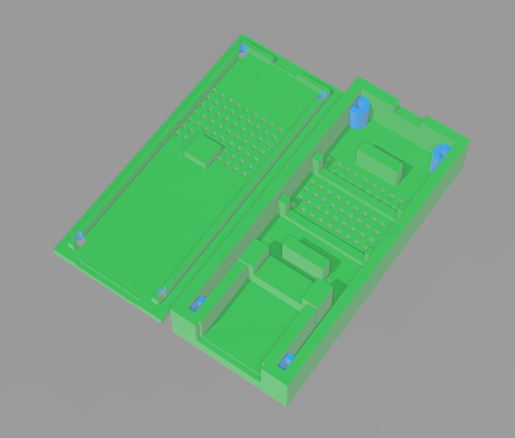
I used Windows 3D Builder, once more impressed by the simplicity and power of this free app, to create the housing. It features
- A snugly fitting place for a vertical USB plug like this one (mounted horizontally…)
- Two narrow slits to press the bent away shielding flaps into for fixation (zoom into the photo of the assembled thing below)
- A place to put the step down converter board into
- Air vent holes (If I’d do the housing again, I’d replace them with slits – they come out a bit tight from the printer)
- A protrusion that presses the mounting-hole-less board into place (it aligns with the inductivity on the board to hold the board down)
- Holes for M2 × 10 countersunk head screws
- Strain relief for a flat cable – adjust to the cable you want to use!
Here’s what it looks like in theory:
Assembly
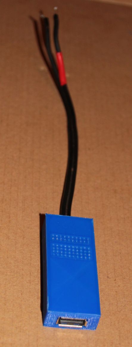
And here’s how it looks in practice:
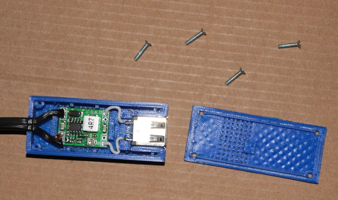
The inner surfaces did not turn out too nice, but everything else was fine without much post-processing. Only thing I needed to do was to free the vent holes from first layer overextrusion with a needle. If I would print a second one, I would replace the holes by slits.
Red marking for positive input…
Two remarks: Do not forget to adjust the output voltage to 5 V. And: when you plan to draw higher currents (specification allows for 3 A, but I doubt the board will deliver it reliably), double-check temperature and thermal dissipation/cooling by air flow. The vent holes may be too small. I did not measure the current, but estimate my setup to draw something around 1.5 A, and it just gets hand-warm.
Make Your Own
You can download the Adapter Housing Files here or from Thingiverse. Alternatively, you may want to have a look on this one on Thingiverse by stanoba.