Motion Sensor PoC: BNO055 and Raspberry Pi Subtleties
The BNO055 is a capable IMU that has on-chip sensor fusion and filtering. Interfacing can be done using I²C and UART. When used with the Raspberry via I²C, you get erroneous measurements because of the I²C clock stretching bug of the Raspberry. Using the UART, results are correct.
To skip directly to the correct connection of the BNO055 Xplained Pro board, click here.
I need a motion sensor…
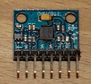
For my upcoming project (which is not a Quadcopter/Drone/Robot project!) I need to track motion, both rotational as well as linear motion, to a few mm/arcsecond precision, using a Raspberry Pi Zero. Looking around, you quickly stumble across the MPU 6050, for which you find cheap breakout boards all over the internet. Hooking up and reading out sensor measurements is a rather simple thing, had it up and running in less than an hour. This post series is a very good quick start guide, and there is at least one python library on github.
But…
The values you get are everything but stable. Browsing the internet you learn about gyroscope drift, short term and long term fluctuations, nervous accelerometers and finally you arrive at the topic of sensor fusion, covariant filters and Kalman filters. This is deep dive stuff! For the curious: Some explanations can be found here. There is an Arduino implementation of a Kalman filter for the MPU 6050 which is supposedly bringing up nice and stable results, but I’d decided upon Raspberry for several reasons, and I could find no implementation for the Raspberry, and did not want to spend time porting code.
Finally, I found out that InvenSense, the manufacturer of the MPU 6050, “provides” ready made code for sensor fusion and filtering, that can run on the MPU 6050 itself, dubbed Digital Motion Processor (DMP). Registering with InvenSense you can download libraries and code examples for using the DMP, but all for different IDEs, not for Raspberries. And: this is proprietary code that is not well documented. It seems that the DMP is a binary code object that is uploaded to the MPU 6050 on start. There is the i2cdevlib which found a way to access and use the DMP (as far as I understand from porting the InvenSense code examples and extracting the firmware blobs), but again, only for Arduino. Certainly it would be possible to port this to the Raspberry – however: not done in a minute.
And there was a last catch: Obviously everyone using IMUs is only (or at least mainly) concerned about roll/pitch/yaw angles – linear acceleration just was not covered in nearly any guide, post or howto on the net. But I will badly need also a suffciently precise and robust linear motion measurement!
Since I want to go on with my project and not with the basics and mathmatics of inertial measurement units (IMUs), I needed to move on.
…and found Bosch BNO055.
Having learned about the term “sensor fusion”, I looked around for affordable IMU sensors that do the sensor fusion and filtering on-chip. I found the BNO055 Xplained Pro board from Atmel. Nearly a factor 3-10 more expensive as compared to MPU 6050 (depends if you order directly from the far east, or as I prefer local dealers), but still what I find reasonable. And it saves me days of work, and work of a kind I am not really craving for, having my project in mind. Finally, it offers nine “degrees of freedom” (9DOF), while MPU 6050 is 6DOF (not that I really need the magnetometer…).
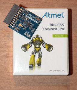
Just as a side remark, in the meantime I learned that the quadcopter/flight control community offers capable boards which from the white papers sound very useful and sophisticated – it seems that cc3d might do the trick at half the price. And perhaps I may still need to try this out – the BNO055 spits out the fused mesurements at about 100 Hz, which may turn out too slow for my project. cc3d claims about 500 Hz.
Interfacing with the Raspberry
For my Proof of Concept (PoC) with the BNO055 I used a Raspberry 3. Adafruit offers a comprehensive guide and a Python library that already covers nearly everything, no need to repeat this all here.
Setting up the Adafruit library
Just a few lines and you’re done:
|
1 2 3 |
git clone https://github.com/adafruit/Adafruit_Python_BNO055 cd Adafruit_Python_BNO055 sudo python setup.py install |
Using I²C – works, but not OK!
The Xplained Pro board is by default set to I²C communication mode, so I started there.
Working out the connections to the Xplained Pro board is easy using Atmel’s datasheet. You only need to connect power and the I²C lines, but the Adafruit library also makes use of the reset pin, so I recommend to connect this also. Furthermore, you may connect the interrupt pin, and there is a RGB LED on board, where each color may be switched when connected to a Raspberry GPIO pin. However, interrupt and LED are not used by the library, so it’s mainly for future use.
Here’s what goes where:
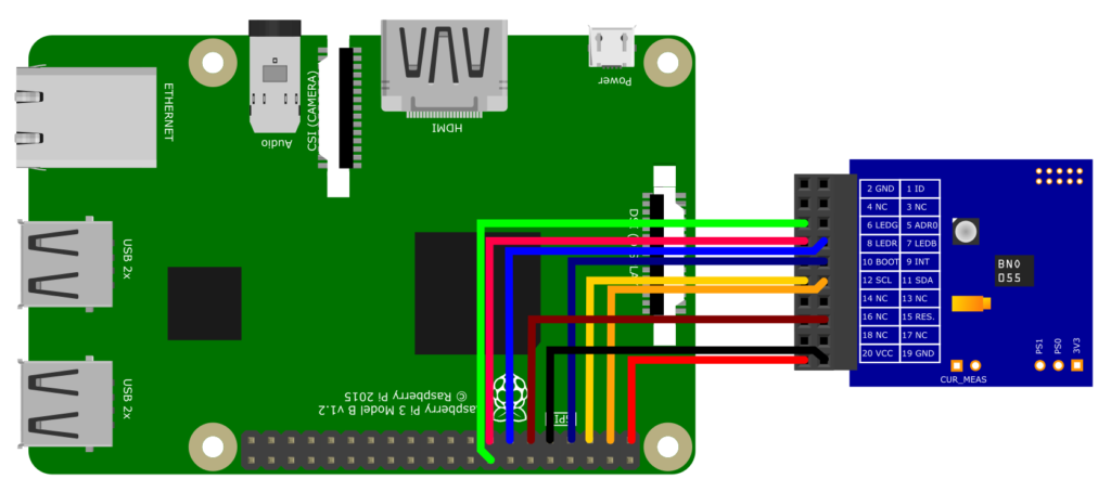
| Raspberry Pi | Xplained Pro | Remarks | ||
| Pin # | Function | Pin # | Function | |
| 1 | 3.3 V | 20 | VCC | |
| 3 | SDA | 11 | SDA | |
| 5 | SCL | 12 | SCL | |
| 7 | GPIO 4 | 9 | INT | optional – Interrupt may be configured to trigger e.g. on motion detection |
| 9 | GND | 19 | GND | |
| 11 | GPIO 17 | 15 | RESET | optional, recommended – Allows to reset the BNO055 chip via GPIO |
| 13 | GPIO 27 | 7 | LED B | optional – The board has a RGB LED on it. Each color may be switched via GPIO. Low means the LED is on. |
| 15 | GPIO 22 | 8 | LED R | |
| 16 | GPIO 23 | 6 | LED G | |
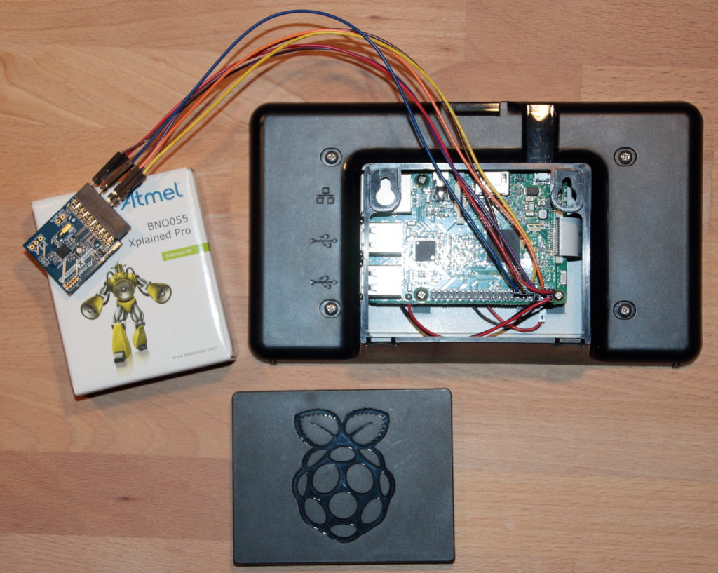
In order to read data, in the files from Adafruit in Adafruit_Python_BNO055 you’ll find a file examples/simpletest.py. At the beginning of the script the sensor connection is defined, starting with bno=…. This line needs the following modification:
|
1 |
bno = BNO055.BNO055(rst=17, address=0x29) |
assuming that your reset pin is connected to GPIO 17. The I²C address 0x29 can be found in the BNO055 datasheet (and be modified using the ADDR0 pin), which can be found along with a lot of other documentation on the Bosch product page.
In addition, I am interested in the linear motion, so I added a few lines in the while True: loop at the end of the script to get these values also:
|
1 2 3 4 5 6 7 8 9 10 |
while True: # Read the Euler angles for heading, roll, pitch (all in degrees). heading, roll, pitch = bno.read_euler() # Read the linear acceleration x_acc, y_acc, z_acc = bno.read_linear_acceleration() # Read the calibration status, 0=uncalibrated and 3=fully calibrated. sys, gyro, accel, mag = bno.get_calibration_status() # Print everything out. print('Heading={0:0.2F} Roll={1:0.2F} Pitch={2:0.2F}\tx_acc={3:0.2F} y_acc={4:0.2F} z_acc={5:0.2F}\tSys_cal={6} Gyro_cal={7} Accel_cal={8} Mag_cal={9}'.format( heading, roll, pitch, x_acc, y_acc, z_acc, sys, gyro, accel, mag)) |
When you now start the code using
|
1 |
sudo python simpletest.py |
the readings come in. Now you need to follow the calibration procedure as described in the Adafruit guide. With the Raspberry 3 it seems to work very nice. But it only seems so! Looking a little bit closer, you’ll notice some oddities. Here are some example readings that show this:
|
1 |
Heading=367.50 Roll=13.41 Pitch=23.80 x_acc=0.12 y_acc=-0.03 z_acc=-0.06 Sys_cal=3 Gyro_cal=3 Accel_cal=3 Mag_cal=3 |
Heading 367.5°? Strange… This goes up to about 370°, and then switches to 10° while turning the chip more and more.
Another one:
|
1 |
Heading=287.50 Roll=3.44 Pitch=43.81 x_acc=1.30 y_acc=-0.04 z_acc=-0.01 Sys_cal=3 Gyro_cal=3 Accel_cal=3 Mag_cal=3 |
Looks totally sane – the only thing: The chip is completely at rest, lying on the table, no movement. But still acceleration in x direction? This comes only at certain positions, not everywhere.
And finally, once in a while a line like this turns up:
|
1 |
Heading=-1760.50 Roll=3.44 Pitch=43.81 x_acc=1.31 y_acc=-0.03 z_acc=-0.06 Sys_cal=3 Gyro_cal=3 Accel_cal=3 Mag_cal=3 |
Obvious nonsense.
In the end it turned out that I did not read the Adafruit guide carefully enough. The Raspberry has a problem with I²C clock stretching, which is actually a hardware bug. Look for “clock stretching” in the Adafruit guide, it’s explained there and you’ll find additional links. Actually, had I used an older Raspberry version, most likely the chip would not have worked at all.
Fortunately, the chip can also be interfaced…
Using UART – OK!
The BNO055 datasheet states that the PS0 and PS1 pins allow the selection of the protocol:
| PS0 | PS1 | Protocol |
| 0 | 0 | I²C |
| 1 | 0 | HID via I²C |
| 0 | 1 | UART |
| 1 | 1 | Reserved |
The PS0 and PS1 pins are availabe at the lower right of the Xplained Pro board (J103 in the Circuit diagram), along with 3.3 V, so just a wire bridge switches the chip to UART mode, and you connect it to the Raspberry UART instead of the I²C pins:
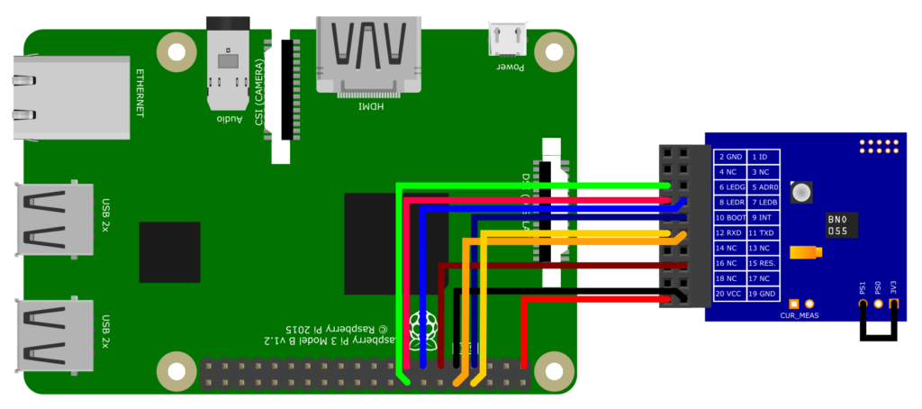
| Raspberry Pi | Xplained Pro | Remarks | ||
| Pin # | Function | Pin # | Function | |
| 1 | 3.3 V | 20 | VCC | |
| 7 | GPIO 4 | 9 | INT | optional – Interrupt may be configured to trigger e.g. on motion detection |
| 8 | TXD | 12 | RXD | UART |
| 9 | GND | 19 | GND | |
| 10 | RXD | 11 | TXD | UART |
| 11 | GPIO 17 | 15 | RESET | optional, recommended – Allows to reset the BNO055 chip via GPIO |
| 13 | GPIO 27 | 7 | LED B | optional – The board has a RGB LED on it. Each color may be switched via GPIO. Low means the LED is on. |
| 15 | GPIO 22 | 8 | LED R | |
| 16 | GPIO 23 | 6 | LED G | |
A few things need to be done on the Raspberry 3 using Jessie:
In /boot/config.txt add the line:
|
1 |
enable_uart=1 |
Then disable the console output to the UART:
|
1 2 |
sudo systemctl stop serial-getty@ttyAMA0.service sudo systemctl disable serial-getty@ttyAMA0.service |
And in /boot/cmdline.txt remove the part console=serial0,115200. A reboot is required.
For a very good and complete description of the serial interface and its configuration on Raspberry Pi 3 read this article.
And finally modify the simpletest.py bno=… line to now use the UART:
|
1 |
bno = BNO055.BNO055(serial_port='/dev/ttyS0', rst=17) |
Now the readings after calibration come in stable and nice – here for the chip at rest:
|
1 2 3 4 5 |
Heading=274.25 Roll=-6.44 Pitch=75.50 x_acc=0.13 y_acc=0.05 z_acc=-0.01 Sys_cal=3 Gyro_cal=3 Accel_cal=3 Mag_cal=3 Heading=274.25 Roll=-6.44 Pitch=75.50 x_acc=0.13 y_acc=0.05 z_acc=-0.01 Sys_cal=3 Gyro_cal=3 Accel_cal=3 Mag_cal=3 Heading=274.25 Roll=-6.44 Pitch=75.50 x_acc=0.12 y_acc=0.04 z_acc=0.02 Sys_cal=3 Gyro_cal=3 Accel_cal=3 Mag_cal=3 Heading=274.25 Roll=-6.44 Pitch=75.50 x_acc=0.12 y_acc=0.04 z_acc=0.02 Sys_cal=3 Gyro_cal=3 Accel_cal=3 Mag_cal=3 Heading=274.25 Roll=-6.44 Pitch=75.50 x_acc=0.12 y_acc=0.07 z_acc=0.03 Sys_cal=3 Gyro_cal=3 Accel_cal=3 Mag_cal=3 |
And also the 360° → 0° switch is coming in correctly now:
|
1 2 3 4 |
Heading=359.69 Roll=8.06 Pitch=-14.25 x_acc=0.10 y_acc=-0.02 z_acc=0.24 Sys_cal=3 Gyro_cal=3 Accel_cal=3 Mag_cal=3 Heading=359.94 Roll=8.19 Pitch=-14.31 x_acc=0.30 y_acc=-0.12 z_acc=0.21 Sys_cal=3 Gyro_cal=3 Accel_cal=3 Mag_cal=3 Heading=0.25 Roll=8.25 Pitch=-14.31 x_acc=0.09 y_acc=-0.32 z_acc=0.03 Sys_cal=3 Gyro_cal=3 Accel_cal=3 Mag_cal=3 Heading=0.50 Roll=8.12 Pitch=-14.38 x_acc=0.06 y_acc=-0.42 z_acc=0.00 Sys_cal=3 Gyro_cal=3 Accel_cal=3 Mag_cal=3 |
Very nice! Project can continue!
Final remarks
The Raspberry SVG image used above I’ve “stolen” from the Fritzing parts library, along with a few more parts. I think I’ll have a closer look on this software in the future – seems like a really nice program!
Only recently I stumbled across this comparison of sensor fusion implementations – worth a read if you’re currently chasing for your solution.

Could you send me your code about UART interface of BNO055 to Pi: [Removed EMail Address from public access]
Thank you very much!
Hi LAM,
will do. Please bear with me – can only do it tomorrow. In the end it is just a very slightly modified version of the sample code in the Adafruit library.
– Hauke
In your article you correctly point out that the Raspberry Pi i2c hardware has a bug which prevents the BNO055 IMU operating correctly. However this can easily be overcome by disabling the standard i2c hardware and replacing it with a device tree overlay. This will allow the BNO055 to be used with the Raspberry Pi. For full details of the procedure please see https://gps-pie.com/pi_i2c_config.htm
Hi Simon,
thanks for this information, very useful!
Btw.: Does anyone know if Raspberry Pi 4 still has the hardware bug?
– Hauke
Unfortunately, I see the same behavior with a RaspPi 4. The solution I ended up going with is not using hardware I2C, but a software implementation which handles clock stretching correctly.
Hey Hauke, great instruction.
One question: how do you get from the acceleration values to the linear movement? Do you integrate the acceleration over time, or does the library provide a lean way to present the “moved” distance from a baseline point?
Hi Hellowitsch,
I must admit that the follow-up project is currently “on hold” – other priorities kicked in. So I yet did not calculate the absolute numbers for distance covered. But I guess indeed that it’s adding up speed x time segments, where speed needs to be calculated from acceleration. I did not dig deeper into the Adafruit code – maybe there’s already something in – it seems that they even constantly improve the libraries. Would be my first place to look.
Cheers
Hauke