RFID Treasure Chest for LARP
I built a treasure chest which opens if a riddle is solved. To prove that the riddle is solved, the players need to put the correct three RFID/NFC tokens (out of several tokens to choose from) onto three RFID readers in the correct order. If they fail too often, a curse is uttered! In this post I describe the hardware selection, the electronics, the assembly and the software.
Motivation and General Description
One of my pastimes is Live Action Role Playing (LARP), although I must admit that I hardly find time for it anymore (Did a lot of it with the LARHGO group several years ago). Recently, I helped to prepare some plot for such a LARP, and for it we needed a treasure chest that opens if the players solved some riddle. I like it when it is not necessary that some game master needs to be present to decide if the players were successful, but the solution is self-contained, i.e. works whatever the players do and where they are at any time. So I constructed a treasure chest that uses three RFID readers onto which the players needed to put correct RFID cards in the correct order. If they did, a compartment within the treasure chest opens “automagically”.
Here are all features of the treasure chest:
- If a RFID card is placed on a reader, a visual feedback is provided – the color of it is given by the actual card, except…
- If a correct card is placed on the correct reader, a different color is shown.
- If all readers have correct cards placed upon,
- A relay creates a ticking noise (like a clockwork that speeds up),
- A servo moves the latch of the compartment aside, so that the spring-loaded lid pops open.
- If the compartment lid is shut, the latch engages again (unless the cards are still in place).
- If the players put any wrong card sequence on the readers 5 times, a nasty curse is uttered from the chest (a recording stored on a MP3 player). This repeats after the next 5 wrong attempts.
- If the treasure chest lid is closed, the electronics engage power save mode so that the power pack lasts the whole game.
Watch this video for a demonstation:
Hardware Overview
The following relevant parts I decided upon:
- An ATmega 328 MCU is the “brain” of the chest. This MCU sports enough IO (digital and analog) for most small projects like this one, it can be programmed easily via the Arduino IDE with all its libraries, and it is reasonably cheap – supposedly the result of it powering most Arduino boards. Also, its power consumption is tiny – especially (and by orders of magnitude) when compared to a Raspberry, which might come to your mind if you think how to handle such a project. I use the MiniCore borad library to programm the ATmega 328 without Arduino board (why? see this blogpost).
- NXP Mifare RC522 13.56 MHz RFID readers – these are available everywhere and rather cheap. They contain everything including the antenna, can be addressed via SPI bus, and there are ready made libraries for the Arduino IDE available. They accept cheap 13.56 MHz RFID/NFC tags which come in all kind of form factors.
- A piece of WS2812 LED “Neopixel” strip for the colorful and animated visual feedback. These are easily programmable via the Adafruit Neopixel library and allow to create nearly any color using individually adressable RGB LEDs. Only thing: They are not that cheap. But still affordable.
- A standard servo as used in model making. Again, ready made libraries for controlling them are available for Arduino. It does not move the latch, it is the latch 🙂 I just use the nylon lever to block the compartment lid directly – its stable enough.
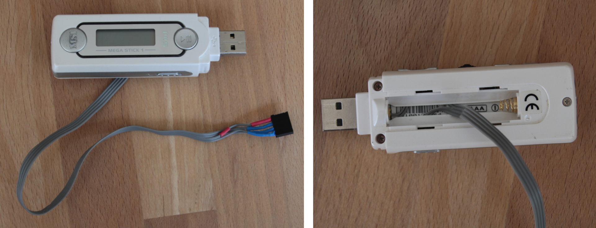
- An old USB stick MP3 player (MSI Megastick 1). Alternatively you may think of adding a SD card reader to the MCU – the MCU itself is powerful enough to play soundfiles, but the idea with the curse came last-minute and I had no SD reader at hand, but this very old MP3 player lying around.
- The LM386 mono amplifier IC. You’ll find it everywhere on the internet whenever it comes to drive a simple loudspeaker. It does not need many external parts to do a decent job, although the sound quality of course is nothing to write home about.
- A standard relay with 5 V rated coil. Originally I planned only to use it for a ticking sound effect to create the illusion of some clockwork setting off to open the latch, and also to mask the technical servo noise (it was a fantasy LARP – too obvious technics may spoil the atmosphere). However, it also came handy to simulate key presses on the on/play button of the MP3 player. This allowed me to switch the player on and start the playback on demand.
- A jumper to enable or disable the curse – since it was a rather spontaneous idea, I wanted to have the possibility to disable it if the other plotters did not like it (they liked it very much actually).
- A 5 V power bank with USB plug (like you find for charging your mobile phone with) as power supply. I used one with 5200 mAh, which was enough to cover more than 24 hours.
Some Challenges
- The RFID readers use 3.3 V logic and are not 5 V tolerant, but the Neopixels need 5 V logic, and don’t work properly on 3.3 V pulses. Also, the servo needs 5 V, as well as the LM386. So I had to work on two power rails. I use a cheap DC/DC converter module to create 3.3 V from the 5 V main supply. On it runs the MCU and the RFID readers, while relay, servo, LED strip and audio parts run on 5 V.
Only caveat: The RFID readers share the MCU power rail, and if the MCU is programmed, they’d get 5 V then. So be sure to make the readers detachable to unplug them while programming the MCU. - Running three Mifare RFID readers in parallel should work directly, but according to a post on stackoverflow it needs special attention. Honestly, I did not try the “clean” approach myself, but I directly went for the extra diodes (D2-D4) and resistor (R9) as stated in the solution – and it works.
- Power consumption of the whole circuit in “energy save” mode was so low that the power bank switched off after some 30 seconds, since it assumed it was not used at all. I added a standard 20 mA LED to the circuit (LED40) just to get enough power consumption to keep the power bank awake.
The Circuit
Here’s the circuit diagram of the whole thing (click on it for a larger view).
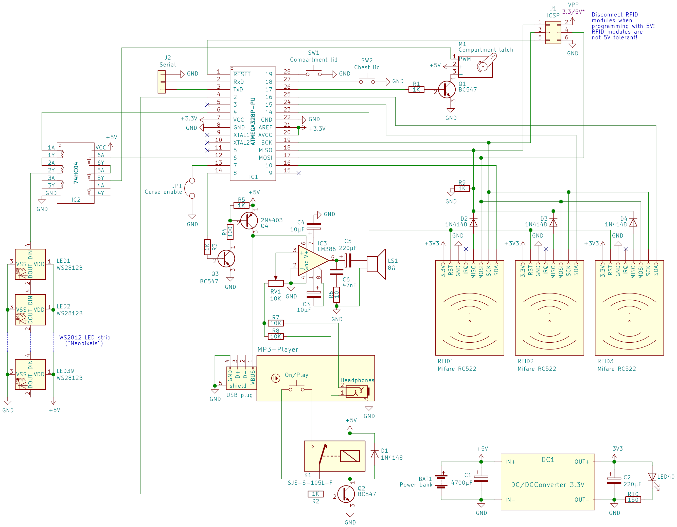
Parts List
| 1 | IC1 | ATmega328P-PU | 3.50 € | Used the DIL packages – makes soldering on stripboard easy |
| 1 | IC2 | 74HC04 | 0.60 € | |
| 1 | IC3 | LM386 | 1.10 € | |
| 3 | Q1 Q2 Q3 | BC547 transistor | 0.10 € | Any general purpose NPN transistor will do |
| 1 | Q4 | 2N4403 transistor | 0.10 € | Any general purpose PNP transistor will do |
| 1 | DIL 28 socket | 0.40 € | I prefer to have the ICs interchangeable – not strictly necessary | |
| 1 | DIL 14 socket | 0.20 € | ||
| 1 | DIL 8 socket | 0.20 € | ||
| 1 | R6 | 10 Ω resistor | < 0.10 € | From a set of resitors, which loweres the price for one down to 0.01 € |
| 1 | R4 | 100 Ω resistor | < 0.10 € | |
| 1 | R10 | 150 Ω resistor | < 0.10 € | |
| 5 | R1 R2 R3 R5 R9 | 1 kΩ resistor | < 0.10 € | |
| 2 | R7 R8 | 10 kΩ resistor | < 0.10 € | |
| 1 | RV1 | 10 kΩ variable resistor | 0.70 € | |
| 1 | C6 | 47 nF ceramic capacitor | 0.15 € | |
| 2 | C3 C4 | 10 μF electrolytic capacitor | 0.20 € | All rated 6 V |
| 2 | C2 C5 | 220 μF electrolytic capacitor | 0.20 € | |
| 1 | C1 | 4700 μF electrolytic capacitor | 0.60 € | |
| 4 | D1-4 | 1N4148 diode | 0.05 € | |
| 1 | LED 1-39 | WS2812 LED strip | 12.- € | I bought 5 m of LED strip, spaced 60 LEDs/m, for about 90.- €, but you can do cheaper. |
| 1 | LED 40 | LED 20 mA | 0.10 € | |
| 1 | LS1 | 8Ω speaker | 5.- € | Salvaged mine from a broken transistor radio |
| 1 | K1 | SJE-S-105L-F | 1.- € | Do not use a solid state relay, but one with a magnetic actuator – it is supposed to make audible clicks! Use any with a 5 V coil rating (alternatively, 3 V, but this requires a minor circuit change) |
| 1 | DC1 | DC/DC converter module 5V → 3.3V |
2.50 € | For 2.50 € I get an adjustable DC/DC buck converter with about 90% efficency – I did not even bother to think if I could build anything myself. |
| 1 | M1 | Servo | 8.- € | Any standard servo will do, but don’t pick a too small one – it needs some stability. |
| 3 | RFID 1-3 | Mifare RC522 | 5.- € | Comes with one credit card sized and one keychain dongle RFID tag. |
| 5 | 13.56 MHz RFID cards | 0.50 € | I wanted to have a few more credit card sized RFID tokens for the riddle – depends on what you plan. | |
| 1 | MP3 player | n/a | I assume you’ve an old one somwhere in a drawer | |
| Pins, headers, jumpers, cable, wire, solder, switches/copper foil, USB-plug… | 5.- € | Usually you’ll have tons of that somewhere in a box… | ||
| Stripboard | 1.- € | Mine is 22 × 38 holes in size | ||
| # | ID |
Part | Price each (ca.) | Remarks |
So, electronics set you back by about 60.- €, unless you’ve most of it on stock or salvaged somewhere. And you’ll need to add the MP3 player, but if none is at your disposal, I’d opt for an SD card reader and let the MCU do the work.
Circuit Parts Explained
Power Supply (BAT1, DC1, C1, C2, [R10, LED40])
Power comes from a 5 V power bank (BAT1), and C1 is there to buffer power drain peaks, e.g. when the relay switches on. It’s really necessary – the MCU tends to crash without it. DC1 is a high efficient step down buck converter that produces 3.3 V from the 5 V. C2 buffers this voltage, but since no 3.3 V part causes power surges, I think you may even omit it.
R10 and LED 40 were a last minute addition to draw enough power from the power bank to keep it awake. Without it, the current drawn in energy save mode was too small and the power bank switched itself into standby.
MCU Plus Housekeeping (IC1, J1, J2), Fuse Bits
J1 is the ICSP socket to attach the programmer to. Warning: Since the RFID readers cannot stand 5 V, but the MCU is usually programmed with 5 V, always disconnect the RFID readers when flashing the MCU! They share the same power rail and will be fried if you forget to disconnect them!
J2 is the header to attach an UART to. I find debugging MCU software a tedious job, and only with the use of serial debug output you stand a chance to track down bugs. You’ll need a 3.3 V logic UART – most serial-to-USB adapters will do the job.
The MCU runs on internal oscillator at 8 MHz – set the fuses accordingly. This is not a high-clock-precision project, the internal oscillator is fine enough. Don’t set 1 MHz – Neopixel library demands 8 MHz. All other fuse bits can be set to your liking – just be sure that you know what you’re doing.
Logic Level Conversion (IC2)
The MCU running on 3.3 V will of course use 3.3 V logic levels. I first tried transistors to convert the signals to 5 V, but this turned out to be ugly, deteriorating the signals beyond usefulness. The Neopixels showed funny colors, but not those I desired. The trick you’ll find all over the internet is to use TTL logic CMOS chips and run them at 5 V. They’ll accept 3.3 V as logic 1, since it is within spec’s, and will output 5 V as a result. The most used is 74HC245, wich has 8 bidirectional drivers. I only had a 74HC04 at hand, which offers six inverters. Two times inverted gives the original signal – so here you are.
Two remarks: I’m sure you can do the logic conversion with transistors only, but my own skills are too bad here – I’d have needed too long to figure it out. Second remark: Also the servo should get 5 V pulses. Mine worked well with 3.3 V pulses directly, but in the circuit diagram I use two more gates as drivers for the servo as well. This is untested – but should be fine, and more appropriate and robust. Perhaps write a short comment if you did it this way.
“Sensors” and Configuration (SW1, SW2, JP1)
These are standard digital inputs which use the MCU internal pullups and connect against ground. JP1 tells the program to (de)activate the curse. SW1 is a microswitch (from an old laptop actually) that closes if the compartment lid pushes it down. SW2 is self-adhesive copper foil on the chest lid (see the assembly section below for a photo). Two disconnected strips on the chest’s body are shortened by a perpendicular strip on the corresponding side of the lid when the lid is closed.
Drivers (Q1, Q2, Q3/4, [D1])
The MCU can only drive a few mA of current, but a relay, the audio parts and the servo need up to a few hundred mA. For the relay and the servo a standard NPN transistor driver is sufficient. By the way: The servo is switched off by the MCU unless movement is required. This saves a lot of energy. As long as the servo can not be accidentily moved by some force applied by the user, it can safely be switched off. I mounted the latch in a way that any pressure put to the compartment lid is perpendicular to the motion direction of the lever, so no movement can be induced from the lid.
D1 is the flywheel diode to shorten currents induced from the collapse of the magnetic field in the relay coil after it is switched off.
Actually, since I originally planned to switch a few more things, I did not use the transistor drivers, but a ULN2803A – still, the method above is sound, I used it for other projects.
For the amplifier the standard driver is not a good idea: It leaves ground free floating when switched off, and I experienced noises from the speaker then. Its better to switch Vcc. So I added a PNP transistor driver. The NPN driver remains, since otherwise the MCU would get 5 V on the control pin – perhaps I am overcautious, but better safe than sorry 🙂 I guess this is one of several parts where my circuit could benefit from someone knowing better what he or she does…
Another remark: I tried the NPN/PNP combination also as logic level converter (see section above) for the LED strip, but the capacitive effects spoiled the signal too much.
Along with the amplifier, the MP3 player is powered up. In hindsight it might be a good idea to switch both parts seperately: The MP3 player needs a few seconds to boot up, and during this time, the amplifier picks up distortions from the MCU, which are audible. But I guess anyone without technical background will hardly notice…
Audio (IC3, C3-6, R6-8, RV1, LS1, K1, MP3 Player)
The amplifier circuit consisting of IC3, C3-6, R6, RV1 and LS1 is the standard gain 200 circuit taken directly from the LM386 datasheet (Figure 12). R7 and R8 join the stereo signal from the MP3 player to a mono signal. To be frank, I used 1K resistors instead of 10K, since I had some volume issues. They came from a different cause (mainly my stupidity), but I was too lazy to switch them back to 10K…
The MP3 player is one of the USB stick kind. Its really old – 128 MB in size, and was picking up loads of dust in some drawer. What made it suitable for me was, that is worked if powered from the USB plug (no need for a separate battery), that it remembered all settings after power down (mainly the volume and EQ), and that it had a simple push button which both switched it on and started playback. When only one file was on it, it was well defined which was played 🙂 I unscrewed the housing, soldered wires to the power junctions at the USB plug (had no USB jack lying around) and the contacts of the push button, and closed the housing again. The power wires were controled along with the amplifier, and the push button was “pushed” by the relay K1. The MCU then needs to power the palyer up, “press” the button once, wait for the boot process, and then “press” the button again for playback.
For audio signal I used a standard 3.5 mm stereo headphone plug to connect to the amplifier.
K1 also is used for its original planned purpose: It makes ticking noises when the compartment opens to create the illusion of some mechanic clockwork running. The MP3 player is off then.
RFID (RFID1-3, D2-4, R9)
The RFID readers do not require much attention – they do all the work, and just transfer the results via SPI. They share the MOSI/MISO/SCK bus lines, and are addressed via the SDA pin. Each SDA pin is attached to a dedicated MCU IO pin to allow to select an individual reader. In theory this should be it, because if not selected via SDA, the reader should put MOSI/MISO to high impedance to not disturb other bus participants. A post on stackoverflow however claimed that the readers misbehave and keep MISO on low when not addressed, pulling the line too low to work. I did not verify this, but directly went for the suggestion in the post: Attach diodes to the MISO pins (D2-4) and a 1K resistor (R9) to the bus line to ensure steep signals. The voltage drop of 0.7 V across the diodes is acceptable. And it works – perhaps someone is willing to try without? Please leave a comment!
Just as a repeat to avoid trouble: Make sure that you can detach the RFID readers while programming the MCU via the ICSP header – the 5 V programming voltage may otherwise fry your readers!
Assembly
Treasure Chest
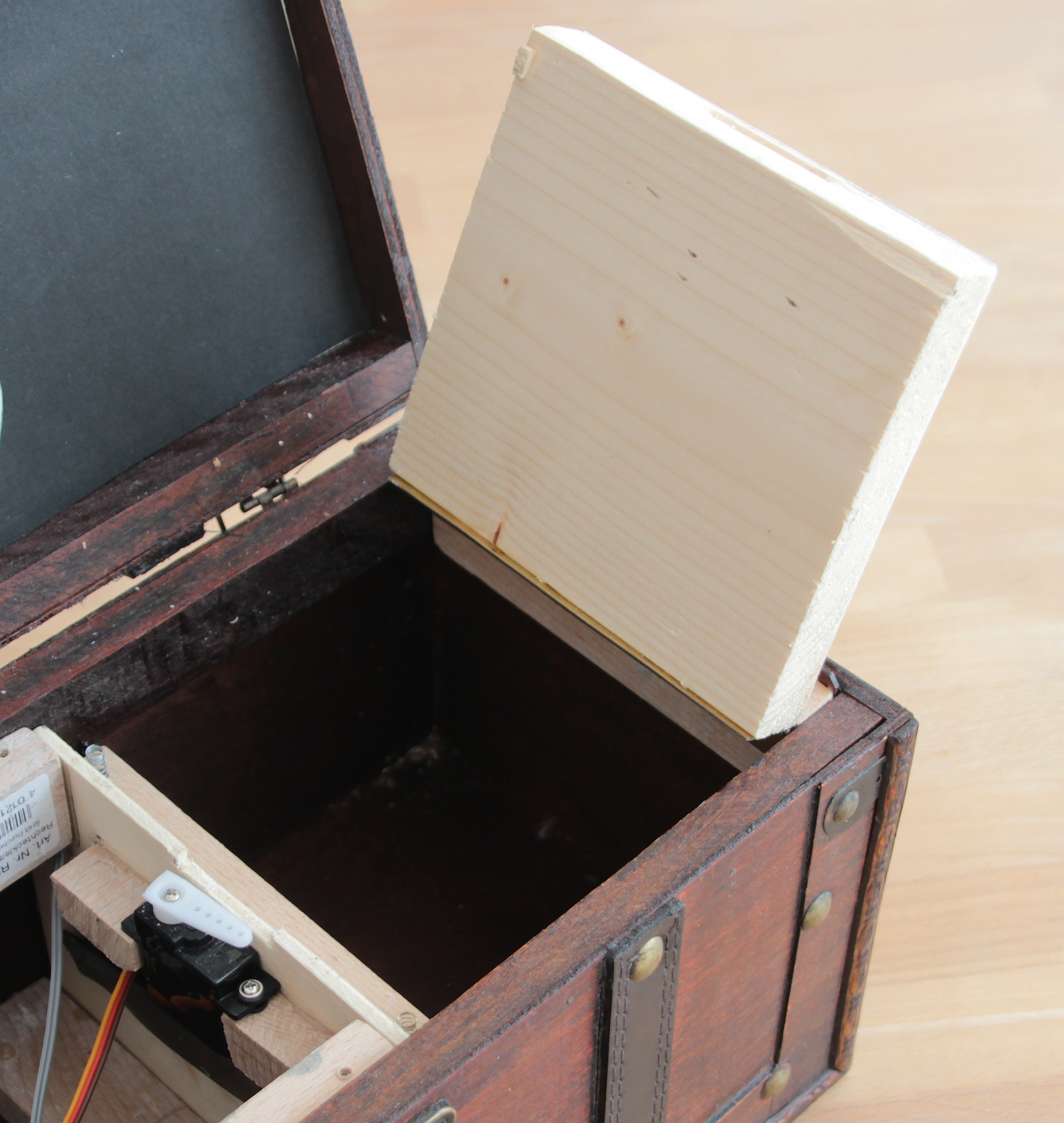
What you use as treasure chest of course strongly depends on what you can get. Mine was from Nanu Nana and really looks like a treasure chest! And was darn cheap with 10.- € as price tag. Things to keep in mind when you look for your chest: You’ll need same space to put three RFID readers underneath and three credit card sized RFID tags beside each other (unless you opt for another form factor). You’ll want a compartment big enough for your treasure, and all the electronics need to go somewehre, including the battery.

Below is an image of the opened chest. The chest lid contains the visual feedback and the loudspeaker. The chest body is covered on the left by plywood under which the three RFID readers are mounted and where the electronics and the power bank are stored below. On top of this I glued paper which symbols for the three RFID card positions. The paper also hides the screws with which I fix the left part – I just did not put glue there, so I can lift the paper to access the screws. On the right the compartment lid can be seen, also decorated with a mystic image. The brass line on the right is the hinge of the compartment lid (a piece of piano hinge). The lid opens upward.

Loudspeaker, LED Strips
Behind the celtic triskelion the LED strips are mounted for the feedback. I used a piece of transparent acrylic glass to which I glued the LED strips with tons of hot glue. I bent them to follow the individual spirals. Each spiral corresponds to one of the RFID readers for feedback.
Onto the acrylic glass I put a black cardboard with the triskele cut out. A bit of standard white office paper was glued behind the triskele as a diffusor. Not visible to the right behind the cardboard, the loudspeaker is mounted to a piece of plywood with loads of holes drilled into to let the sound travel through it. Unfortunately I did not take pictures without the cardboard, and its difficult to remove it now without damaging it – so use your imagination 🙂
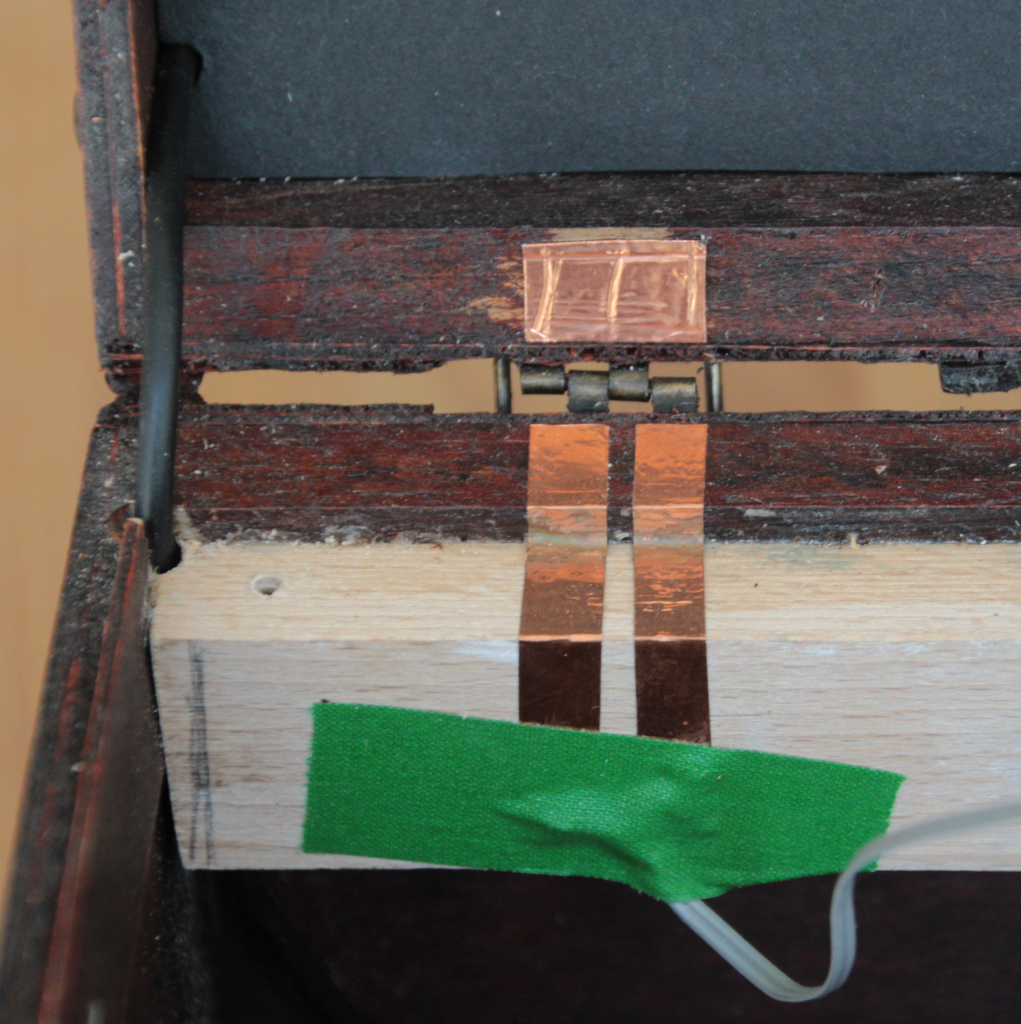
To the lower left of the lid you can see the cable that connects all to the electronics in the chest’s body. The copper parts are the sensor for the chest lid (see below).
Electronics, RFID readers
As always, I use stripboard to build my projects. And as always, the project evolves during the realization, and the thing looks rather ugly in the end… Besides of that, not much is remarkable – except the umpteenth reminder to make the RFID readers detachable to avoid killing them by 5 V programming voltage. Here’s an image of my ugly stripboard result, screwed below the plywood cover with the RFID readers. You can see the USB plug for the power bank, the 3.5 mm stereo plug for the MP3 player and the detached RFID readers cable.
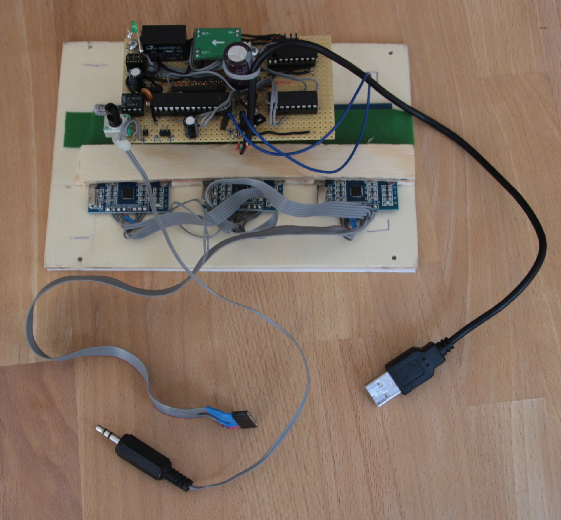
Seen from the side you can see how I put the RFID readers into slots made of plywood. I did not want to use screws, since the plywood is rather thin (and must be thin for the NFC signals to work through it). The green tape is to fixate them.

Compartment, Servo/Latch
The compartment lid is just a piece of wood (thicker than the plywood) which is mounted atop the treasure compartment with a piano hinge. For the latch, I carved a slit into the side of it, into which the lever of the servo slides. In this configuration the user can not move the lever accidentilly by applying force to the lid.
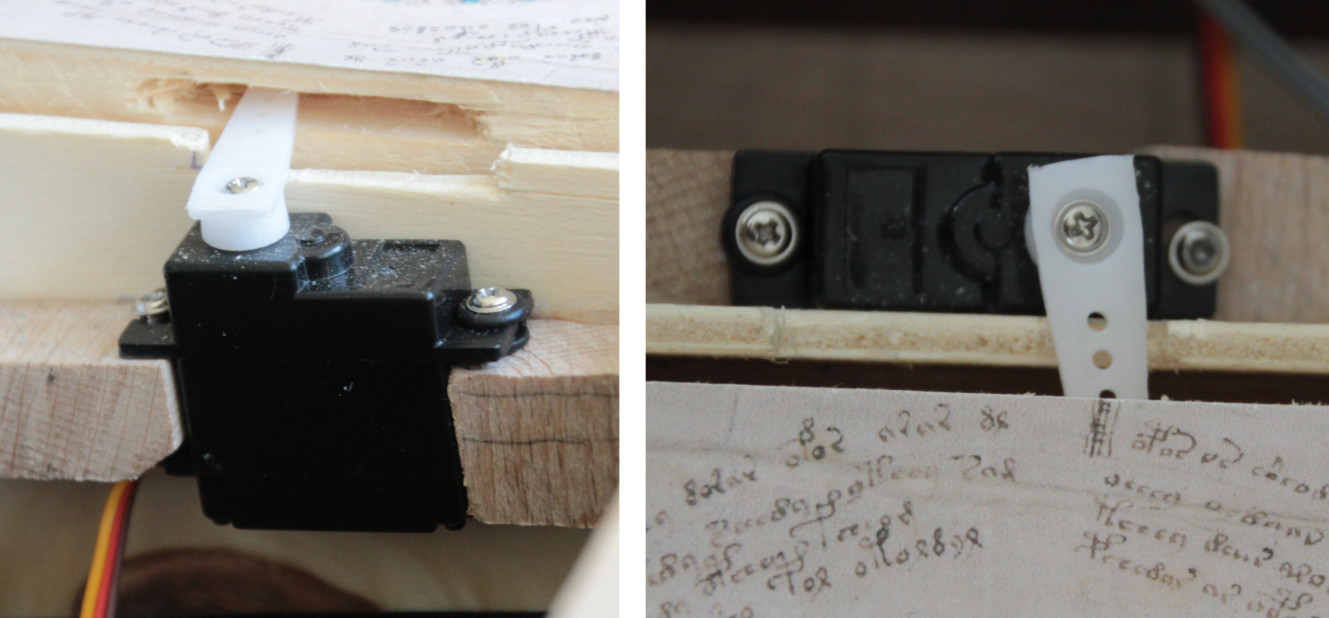
The lid is spring loaded. When the servo lever moves out of the slit, the lid snaps open. You can see the springs (taken from old, dried out ball pens) in the following image: They are in holes left and right on the abutment of the lid.
Sensor Switches
SW1 is a standard microswitch which I salvaged from an old laptop lid. In the image below I tried to highlight it among all the hot glue I used to attach it. You can also see one of the springs that push the lid open. The switch will only engage if the user pushes down the lid actively.

SW2 is a bit special: I used self adhesive copper foil to build a very flat switch that sits right between lid edge and body edge. The copper foil on the lid shortens the two copper foil strips (with cables soldered to them) on the body when the lid is closed:
Powerbank, MP3 Player
The power bank goes into the space below the RFID readers, and I use self adhesive velcro to attach it firmly, but removable. Same holds true for the MP3 player. Here you can see the cable coming out from the player:
Software
The source code/sketch is available for download here. It may be used and modified for non-profit purposes without further notice. Commercial use, also of modified versions, is OK only with written permission by me. If you use the code, a comment below or an email would be really nice! If you publish anything based on this, please honour my work and publish my name or the link above along with your publication. Thanks!
I tried to write it in a comprehensive way, with meaningful names for variables, constants and functions, and added comments wherever I found helpful. Write a comment below for questions.
The general concepts are not really complicated, just a few remarks that are worth mentioning here.
Interrupts
The Neopixel library is timing-critical, and also my ticking of the relay may sound not as nice as it does if it gets interrupted. The serial output by default utilizes interrupts, so I had strange effects when using it for debug, like funny colors from the Neopixels. Solution is easy enough, just included
|
1 |
noInterrupts(); |
into the setup() function. As a result, serial output may become sluggish, so I’d suggest to keep serial output short.
RFID Reader Interference
Initially I just used the combo
|
1 2 3 4 |
[...] if (RFIDReader.PICC_IsNewCardPresent()) { RFIDReader.PICC_ReadCardSerial(); [...] |
to access the RFID card data. When I finally put the readers into place, I had a nasty surprise, since the cards were not identified reliably. Mainly the middle reader had problems – which of course is a strong indication that the RFID readers distort the signals of each other. Solution was easy again – I found it in this Arduino forum post – I soft-powered off the unused readers, and I added the Antenna on/off command that I found in the MFRC522 library reference:
|
1 2 3 4 5 6 7 8 9 10 11 12 13 14 15 16 17 18 |
RFIDReader.PCD_Init(); delay(5); // wake reader up RFIDReader.PCD_WriteRegister(RFIDReader.CommandReg, (byte)0x00); delay(25); // activate antenna RFIDReader.PCD_AntennaOn(); // do something [...] if (RFIDReader.PICC_IsNewCardPresent()) { RFIDReader.PICC_ReadCardSerial(); [...] } [...] //done // switch off antenna and send reader to sleep RFIDReader.PCD_AntennaOff(); RFIDReader.PCD_WriteRegister(RFIDReader.CommandReg, (byte)0x10); |
This did the trick. So, now only one reader is on at a time, and no interference happens. As a bonus, power consumption goes down considerably! The delay() after the wake-up should be there, because the MFRC522 datasheet mentions that after setting the power-on register, it may take up to 1024 clock cycles for the chip to really wake up (see section “8.6.2 Soft power-down mode” in the datasheet). 25 ms may be a little long, but just to be on the safe side…
Integrating Your RFID Tokens & Defining Valid Token Sequences
The part in the code that contains the RFID token identifiers is of no use for you as it is, since you need to insert your RFID token IDs. In order to get them (assuming that you have no other means of reading them), here’s a way: Build the circuit and program the MCU, then attach the MCU UART to whatever you’ve at hand (e.g. an USB to serial adapter with 3.3 V logic level and use PuTTY) and power up the thing. Your terminal should use 9600,8,N,1 as serial config (with PuTTY just enter speed 9600, all else is default anyhow). Now put each RFID token to one reader – you’ll get the ID in the output:
|
1 2 3 |
1: CardID 12345678 - Card #0; last was: #0 2: CardID 0 - Card #0; last was: #0 3: CardID 0 - Card #0; last was: #0 |
In the example, 12345678 would be the ID to use later in the code.
By the way: Of course you can go further and add cryptographic keys to the cards to make your system tamper-proof, but that seemed a bit too much paranoia for my purposes, so I kept it simple and used the built-in card-IDs. There is a tiny chance that you’ll get two cards with the same ID, since I assume that the IDs are randomly generated. The ID is four byte (usually – it seems that there exist other cards, but my code currently will only use 4 bytes), so the chance is about 1:4.3 billion – I’d take the risk 🙂
When you have the IDs, put them into the Cards[] array and adjust NumberOfCards:
|
1 2 |
unsigned long Cards[] = {12345678, 87654321, 1020304050, 4266647, 18273645}; int NumberOfCards = 5; |
This IDs later will represent your tokens #1, 2, 3, 4 and 5 (as an example). #0 would mean: No card or unknown card.
Master Keys
I also included master keys – I used the keychain tokens that came with the RFID readers for this. Master keys will open the compartment directly without any ado – this is if you want to quickly change the content of the compartment as game master. I also hard-coded master key #0 (they start with 0 just to confuse you…) to also trigger the curse – this is to adjust volume.
To add your master keys, do the same as with the other tokens, and adjust these lines:
|
1 2 |
unsigned long MasterKeys[] = {81726354, 54637281, 1010101}; int NumberOfMasterKeys = 3; |
This defines master keys #0, #1 and #2 as an example.
Sequences
A sequence is any combination of three cards that are put on the readers at the same time. To define which sequences will open the compartment, the following lines are in the code and need adjustment to match your ideas:
|
1 2 3 |
#define NumberOfValidSequences 2 #define NumberOfValidCardsPerPosition 2 int ValidSequences[NumberOfValidSequences][3][NumberOfValidCardsPerPosition] = {{{1, 4}, {2, 5}, {3, 3}}, {{1, 5}, {2, 5}, {4, 5}}}; |
The first line in the example code above tells that there are two valid sequences defined (I only used one, but do as you like…).
The next line says that there are two valid cards for each position (again, I only allowed one card, but may change this if the chest is used on a follow-up LARP to have a spare set of cards ready. In other words: It allows for redundancy.).
The third line defines the valid seuqences.
So the example above reads like this:
- Sequence 1 is fulfilled if on Reader #1 either token #1 or token #4 is present, on Reader #2 token #2 or #5 would be OK, but on reader #3 it must be token #3. So valid token placements would be: 1-2-3, 4-2-3, 1-5-3 or 4-5-3.
- Sequence 2 is fulfilled for combinations 1-2-4, 1-2-5, 1-5-4, 5-2-4.
Other Things You Need to Take Care of
Observe the following lines:
|
1 2 3 4 |
#define LatchMaxAngle 60 #define LEDsPerReader 13 // Have 39 LEDs in the LED strip, devided by 3 readers #define CurseDuration_ms 6000 #define WrongSequencesForCurse 5 |
LatchMaxAngle must meet your servo configuration. In my case the latch moved between 0° and 60° (well, actually it moved between 0° and 90°, but somehow this corresponded to 60° in the servo command… Trial and error needed.). If yours does need something other than 0° as second position, you’ll need to modify the code and add a LatchMinAngle also – you’ll work it out, I’m sure. But since the position of the lever on the servo is adjustable by how you fix it with the screw, I’d be surprised if you need anything but 0°. Still, if your servo needs to move in the other direction as compared to mine, you’ll need to modify the code: Latch control is in the function OpenCompartmentLid. Also, in the setup() function you’ll need to adjust the angles. Hope my code comments help you.
LEDsPerReader defines how many Neopixel-LEDs in the strip are used for the visual feedback for a single reader – in my chest its one spiral arm of the triskelion. Your complete LED strip should have 3 × LEDsPerReader LEDs in total.
CurseDuration_ms is the length of your curse sound bit in milliseconds. Its how long the MCU waits before switching off the MP3 player and the amplifier again. I did not find the delay() function to be too precise, so be sure to test this and adjust as needed.
WrongSequencesForCurse defines how many wrong sequences will trigger the curse to be uttered. By default it will happen after another WrongSequencesForCurse player’s errors again and again, but if you watch the comments in the code you’ll find that you can switch the curse to “one time only” – in this case it happens once after WrongSequencesForCurse wrong attempts, and only then.
Closing Remarks
For me, the chest worked very well on the LARP! The players solved the riddle very fast and evaded the curse 🙂
In case you create your own treasure chest based on my examle, I’d really love to hear about it! Post a comment! Thanks.
Alternatives
Doing some vanity googling I became aware of two similar projects – perhaps they add inspiration to your project:
- A project on instructables by kurt-beheydt
Good if you want to use just one RFID reader. With this project you have to swipe the cards one after the other in correct order. - A commercial, ready-to-go set by Robot Geek
Surprisingly cheap, but rather small.
Credits
Special thanks to my girlfriend for helping with the mechnics and assembly, and for all the patience!
Thanks to all the contributors to the Arduino project, the used libraries and board definitions. Without this, writing the code would have been way(!) more work!
Circuit diagram drawn with KiCAD. Graphics and photos prepared for web with Gimp. Video edited with Aquasoft Stages.