Simple Capacitive Water Sensor for a Water Container
From simple, standard electric cable I built a capacitive sensor to assess the water level in my water container. While the circuit was replicated from this blog (thanks for sharing!), I’d like to share how I built the actual capacitor.
The Situation
Only a few days ago I posted my successful implementation of an ultrasonic, waterproof sensor for measuring the water levels in my rainwater barrel. And while that post is still valid, the method turned out to be not as stable as I wanted. Again, condensation was the problem, drops running down the cone caused the sensor to show wrong levels ever so often. Also, I had problems with the fill hose drifting into the sound window at occasions, again spoiling the measurement. I guess with some effort all this could be fixed, but I was a bit fed up and doubted the long term stability of that approach.
With little hope I tried if an infrared distance sensor I had lying around might work, but as I suspected, water is transparent to infrared light, so this got me nowhere. I tried to put a ball into a tube, put the infrared sensor on top of the tube and let the ball float on the water inside the tube. But the opening angle of the sensor was too big, so it did only work for very short distances.
Came to my mind that I tried around with capacitive sensors for measuring soil humidity. The general concept (I followed this post past then) worked very well – I used double sided PCB material as capacitor – but I never could get it watertight. As soon as I inserted it into soil, I got a short. I tried different sprays and sealings, but I never got it right. I suppose epoxy resin should work, but that’s too messy for me. So for soil humidity I finally followed what many people did – I ended up using these cheap, pre-made sensors, which work decently well.
Elongated, Watertight Capacitor
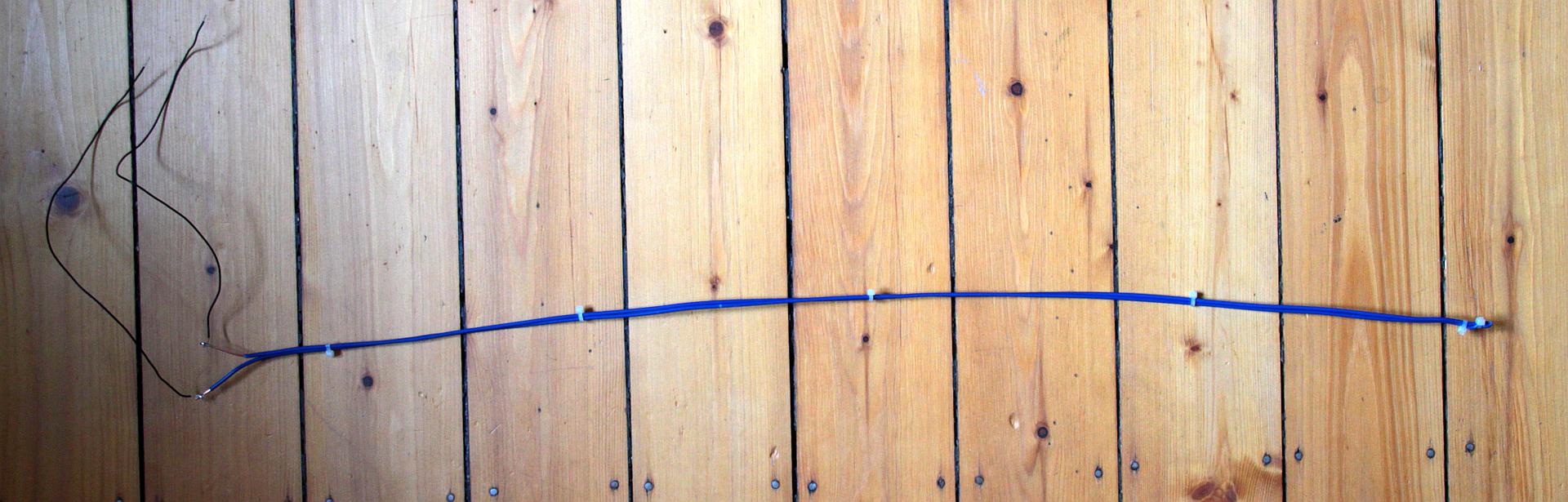
So if I wanted to use the capacitive measurement principle with my barrel, I’d need a ~70 cm long, watertight capacitor, and I finally had an idea how to get one! I used a bit of standard, 1.5 mm² cross section power cable, which usually goes into the wall for the 230 V power network in your home – it runs under the type NYM in Germany – not sure how international this is. But basically the copper wire you use for home electricity – the actual cross section would not matter too much I suppose. Important however: You need solid wire, not litz wire – you’ll see why in a second. This wire is insulated with PVC, and that should be pretty watertight. For the capacitor I’d need two, not connected wires in parallel, which would leave me with an open end in the water, again difficult to get watertight long-term. So what I finally did is this:
- Took a 3-wire NYM cable, the length of it bit more than twice my barrel height (~160 cm),
- Stripped it off its outer insulation, so I get the individual (still insulted) wires,
- Took one (the blue of course – it’s for water 🙂 ) and bent it in the middle,
- Now I carefully bent it back and forth, over and over again in the middle, until the copper wire broke (needs perhaps 20-30 times bending – and this only works with solid copper wire), while watching not to hurt the wire insulation,
- Then pulled back the copper in the insulation on one side with pliers, so that a gap separated the now two copper wires,
- Now put the two copper wires in parallel and fixated them with zip ties.
Here is my result:
A close look at the bending zone: The insulation is undamaged.
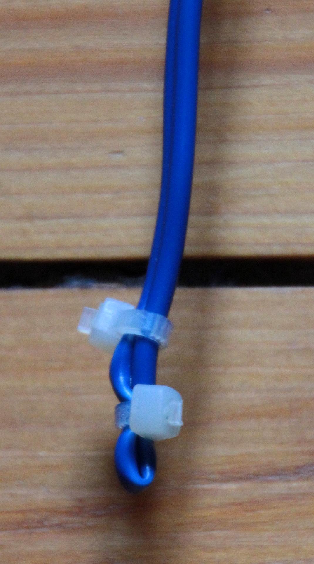
For good measure, I also put a thick glob of hot glue around the end, also as mechanical protection.
Electronics
Since I could not remember the post I originally tried for my soil sensors, I googled again and this time found this post with a slightly different circuit, but the general principle is the same. The self-made wire capacitor probe is used with a NE 555 as an oscillator (the standard application “astable multivibrator”). The oscillation frequency depends on the capacity of the capacitor. Immersing the two wires into water would change the dielectric characteristics of the capacitor, which results in a change of capacity, which again results in a change of frequency of the oscillator. Using the ATmega 328P in my barrel water pump control, I measure this frequency using the pulseIn() function, and voilà, I could infer the water level in my barrel with a bit of calibration.
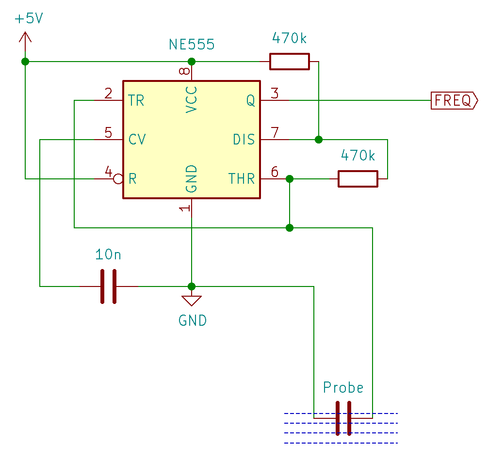
I expected that I’d need to play around a bit with the resistors to get into a frequency range that the MCU could measure (It could go up to somewhere near 100 kHz, although I’d recommend to stay about an order of magnitude below), but it turned out that with my setup having the original 470 kΩ resistors I was somewhere between 1 to 20 kHz, which is just right.
Important: Make sure to do your setup and calibration with all cables and wires in the final state – the capacitor alone in my prototype had me between 17 and 8 kHz (dry to immersed in water), but after I attached the wires to connect it from the barrel to the MCU housing, the added capacity from that cable pushed me down to 5.4 kHz and 2.3 kHz (dry vs. wet). Perhaps I should have tried to go higher again for a bit more resolution, but I did not bother. In the final setup I can measure my water levels in ~200 steps, which is more than sufficient.
Code
Here are the relevant code snippets for Arduino/Atmel MCUs.
|
1 2 3 4 5 6 7 8 9 10 11 12 13 14 15 16 17 18 19 20 21 22 23 24 25 26 27 28 29 30 31 32 33 34 |
[...] #define WaterSensorPin 15 // Frequency in from capacitative water sensor [...] void setup() { [...] pinMode (WaterSensorPin, INPUT); [...] } void loop() { [...] static unsigned long HalfPulse1, HalfPulse2; static unsigned long Measurement; [...] // The NE555 square wave is asymmetric, so let's measure both high and low pulse phase HalfPulse1 = pulseIn(WaterSensorPin, LOW, 1000); // returns 0 if timed out if (HalfPulse1 > 0) { // technically this measures the second half wave of the next pulse - but this should introduce only a small error. HalfPulse2 = pulseIn(WaterSensorPin, HIGH, 1000); if (HalfPulse2 > 0) { Measurement = HalfPulse1 + HalfPulse2; // expected values: Cask completely empty = ~5.4 kHz --> Pulse width ~185 µs - Cask full: ~2.3 kHz --> Pulse width ~430 µs } else { // defined value in case of an error Measurement = 1000; } } else { // defined value in case of an error Measurement = 1000; } [...] } |
For better readings, in my final code I do several measurements and pick the median (not the average!).
Result
What yet remains to be seen is the long term stability of this setup, but I’m rather optimistic here! Problem solved…
Update after a few months: Readings are stable enough, a bit fluctuating, but good enough for monitoring the general water level. Also, I seem to observe a temperature dependency of the readings, which I may investigate at a later point. Happy!
This is a promising project for water level monitoring. I too have an underground tank, which I would like to monitor water level.
How is it holding on?
Can you please share the Arduino sketch you have used?
Thanks
Hi Nithin,
my sensor is working well since June, so I’m positive that it is really a stable solution. Measurements are not too precise, sometimes a bit fluctuating, but good enough for my purposes. I seem to observe a temperature dependency of the readings, which I at some point will have a closer look at, but for now, I’m happy and have a working solution.
As for the code: Updated my post.
– Hauke
Thanks a lot. I appreciate the effort.