Replacing Fabtotum Hybrid Head v1 Hotend with E3D Lite6
I replaced the stock hotend of the Fabtotum Personal Fabricator Hybrid Head v1 by an E3D Lite6 hotend (The full metal V6 should work the same way). In this post I describe the steps to remove the old hotend, get in the new hotend and the simple modifications to the firmware that were required.
A remark right in the beginning: Had I known how difficult and fiddly this project would turn out, I’d perhaps never have started it but would have gone for a dedicated print head with the E3D as others did, e.g. here. In the end I decided to remove the E3D again and build a seperate print head (I will write a blogpost on this as soon as I am done). The hybrid head is too crammed and strangely designed, it is a pain to fit something in that was not supposed to be there from the beginning. Still, I do not regret doing it – I learned a lot about the printer, and many things are still valid and needed for the new, individual print head.
If you are willing to remove the milling motor from the hybrid head, losing the milling capabilities, and can also live without print cooling (e.g. if only printing ABS), it is well worth to read this blog post, or also have a look at this page, but make sure to follow the thermistor steps I outline below, since they are missing in the mentioned page.
To skip directly to the parts interesting for you, use the table of contents below or on the right.
Table of Contents
Why? Overheat Protection Killed my Hotend
The Fabtotum Personal Fabricator originally was a very successful Idiegogo campaign to build a CNC machine that could 3D print, mill and laser with a decent working volume. They fulfilled their campaign, and continued with an upgraded “Pro” model (Fabtotum Core PRO) which cost close to 3,000.- €. However, in the end the company did not make it, they filed for liquidation mid 2018. I got my printer a few months later on eBay from a backer for ~250.- € and took my first steps into 3D printing and CNC milling with it. In general, the machine is not too bad, but not too good either. I pulled my hair about it several times, but in the end I was able to get decent prints with PLA, PETG and PP from it. The main criticism I’d utter would be that it is very difficult to maintain because of some design decisions I’d call not so clever. I understand that the Pro model was much better in that regard.
Also, software was not fully mature, and in the end this caused me breaking my hotend beyond repair. Here’s what happened: I wanted to print something from polypropylene, which is possible with the Fabtotum – I successfully did this before. You need to go to the printer’s limits: I print it at 230°C nozzle temperature, and heated bed at 100°C, which are the max values for my setup. Now there’s one problem: When you heat up the nozzle and bed before the print starts, and then the nozzle moves in to start the print, the hot bed causes a sudden jump of nozzle temperature up to 240°C and even above. This causes the printer to trigger it’s overheat protection, and with a ghastly sound it moves the nozzle to one corner, stopping the print. A good countermeasure is to manually turn down nozzle temperature to ~220°C while it waits for the bed to heat up, but once in a while I forget this, stupid me.
One problem of the overheat stop is that the printer becomes unresponsive – you basically can’t do anything but powercycle it. When the interruption happened this time to me, I realized that from the printer UI the print is shown as “paused”, which I’ve overlooked so far. So my thought was this time: Why not just resume the print? So I clicked on “Resume print”.
And that was a stupid idea.
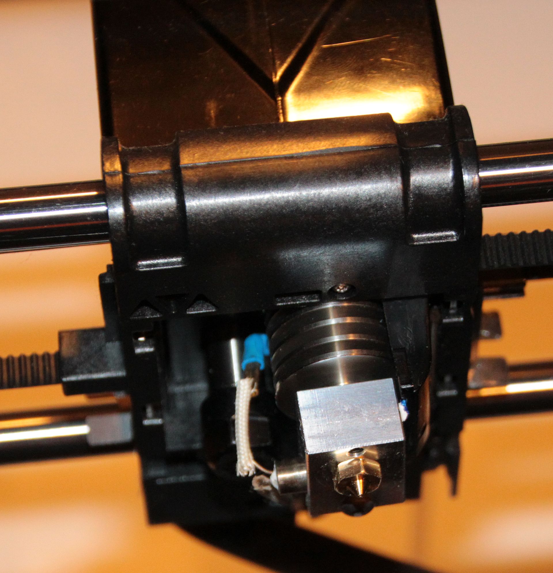
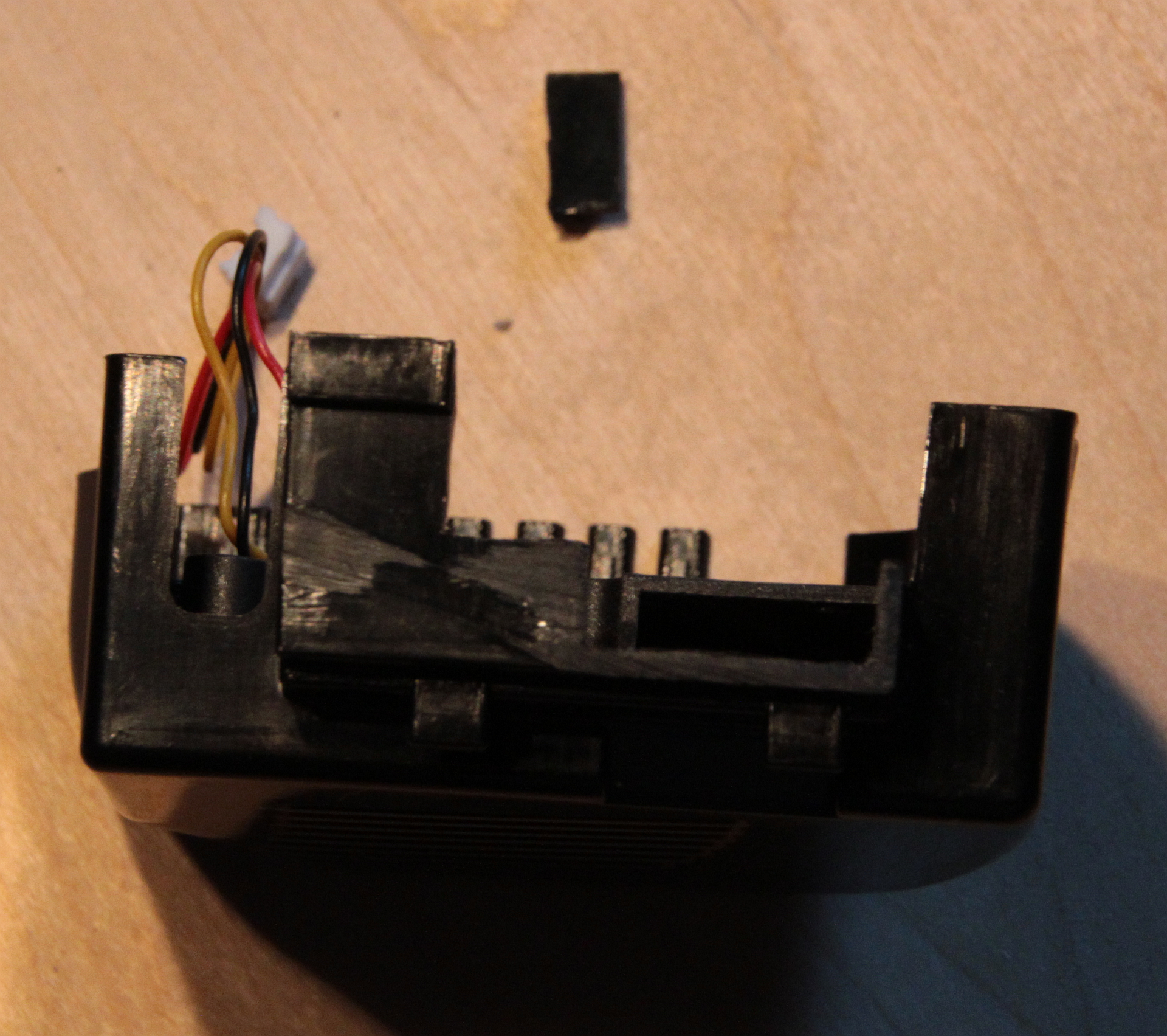
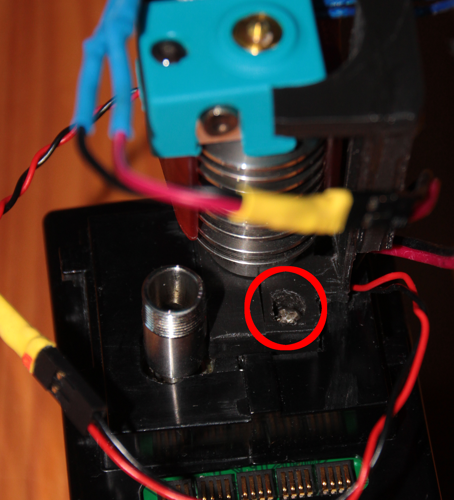
Actually, the printer resumed in a way: It switched on bed and nozzle heating again, but everything else remained stuck, no head movement. I started clicking around, trying to understand what was happening and looking if I somehow could get it going again, and while I did for 30 seconds or so, everything went hotter and hotter. I suddenly saw that nozzle temp was already at 300°C! I immediatly switched off the printer, and removed the head from it’s mount. But it was too late! The heatbrake plastic (yes, it’s plastic! I never understood why – looked stupid to me from the beginning on) melted, giving off the magic smoke, and the hotend was set askew:
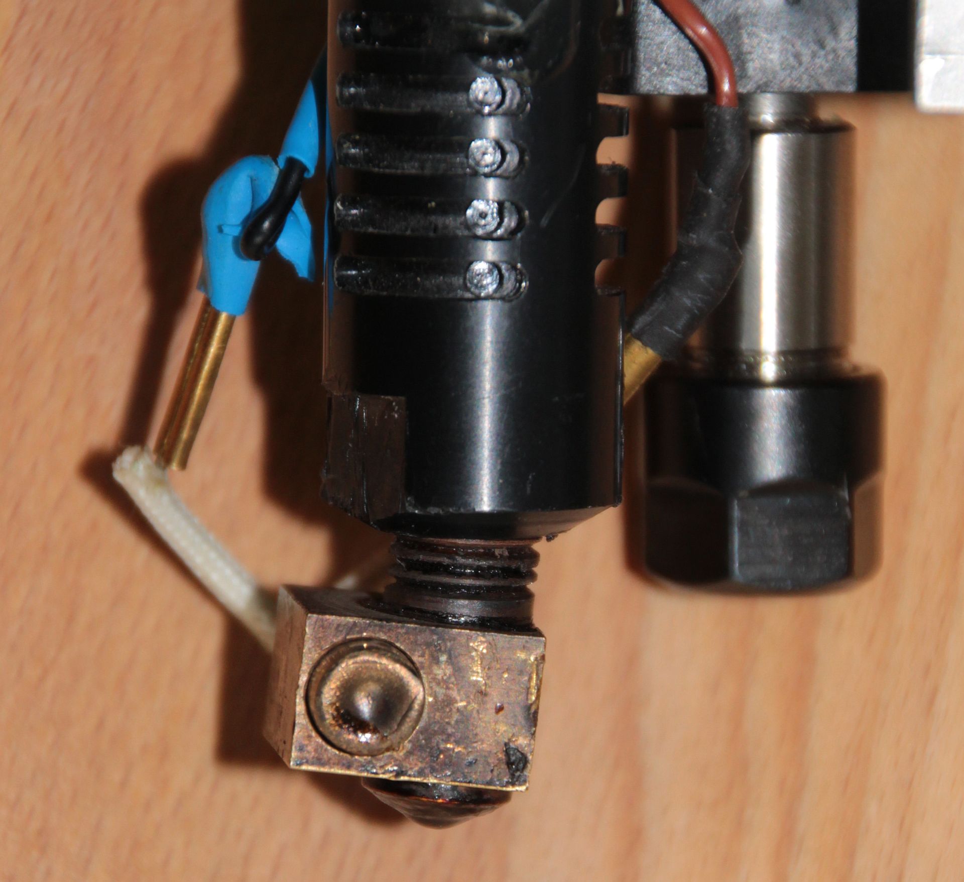
Actually, it looked even worse – the picture was taken not immediately after the desaster, but after me already working on the head for a while to prepare the replacement.
This certainly was beyond repair! And thats why I installed a new hotend.
Selecting the New Hotend
I first tried to find kind of the same hotend, since I remeber seeing such a plastic thing somewhere, but I gave up quickly, since my mind was already wandering in the direction of E3D, who have quite a reputation for good hotends. The famous Prusa printers are sourcing their hotends from E3D. Still, I wanted to keep the price as low as possible, since I backed the Snapmaker 2 campaign and hopefully will have a shiny new A350 3-in-1-CNC on my bench by July. Nevertheless I’d loath having the Fabtotum not in working condition, and also I’d need some prints before July. The E3D V6 has a perfect reputation, but in the end I went for the Lite6, mainly because it is cheaper. The spec’s are similar to the old, broken hotend, which not only holds true for the temperature range, but also in terms of size. Or so I thought – it was not that easy, but I come to this later. So the Lite6 it was, and I stopped looking further. However, the V6 should work the same way, since it’s dimensions are comparable to the Lite6. The Lite6 could still suffer from overheating, but all that will happen is that the PFTE liner will degrade, and that’s easy and cheap to replace.
Removing the Old Hotend
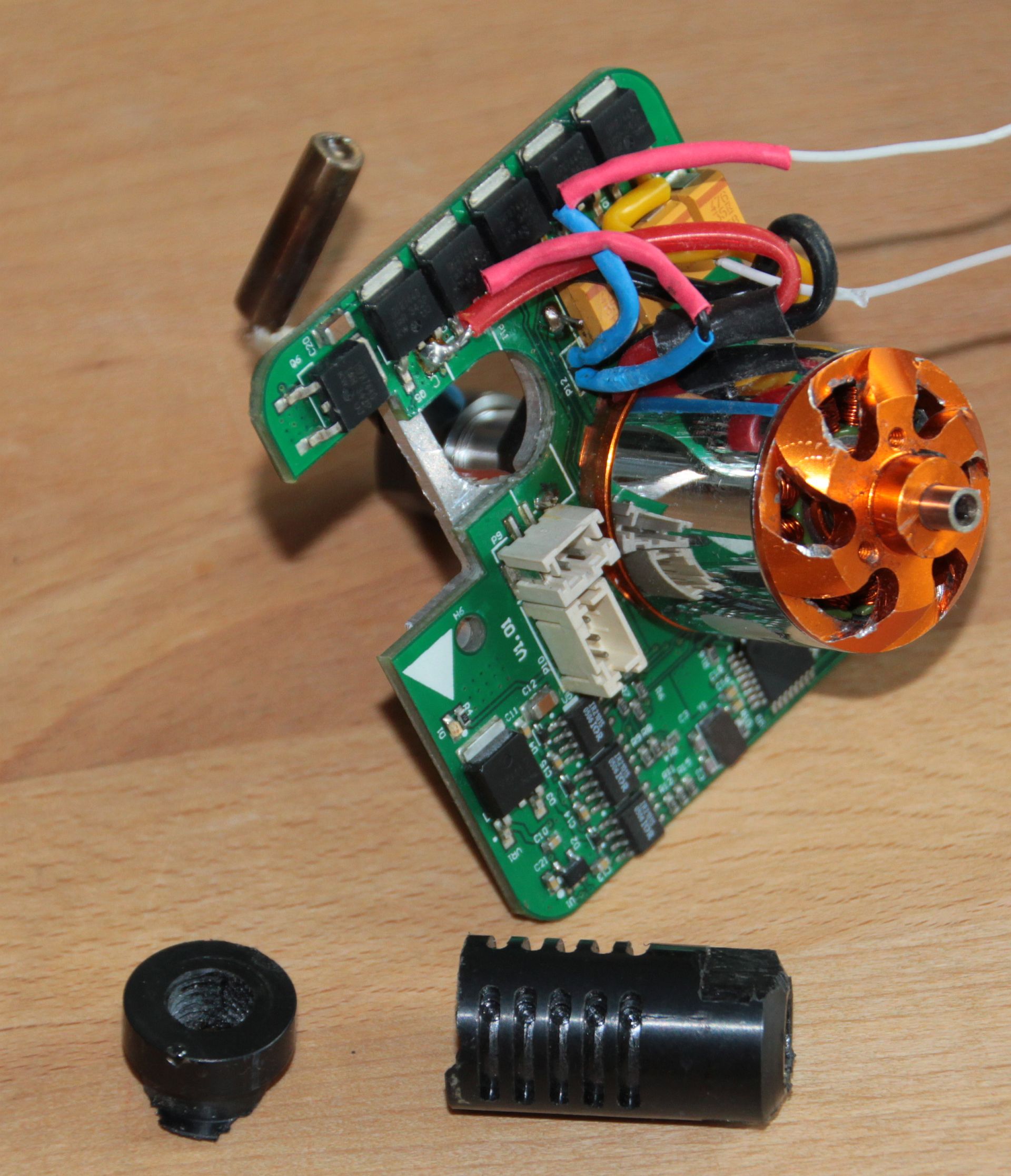
Basically, all that needs to be said is well said on this page (Only thing I did different: Did not use a Dremel, but a plain metal saw, sawed the plastic half through and then used two screwdrivers inserted into the plastic cavity and applied enough force to break the plastic tube at the sawed point), or on this page. Take care to not cut the heater and thermistor cables too close to the PCB! You’ll later need them, and it is extremely difficult to solder them on later due to the metal plate right under the PCB. Also, try to be gentle with the plastic tubes that guide the filament through the upper head – you’ll use them later again and want them intact.
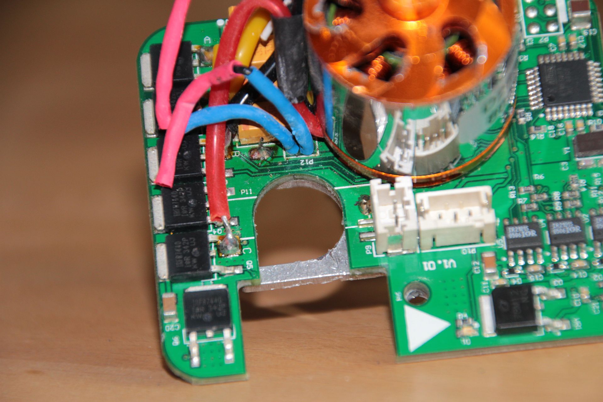
Actually, before falling back to this brute force method, I tried to dismantle the whole head in a more reversible way, but I did not succeed. I went as far as removing the rotor from the milling motor (which already is a feat), but then I was stuck – I could not figure out how to unscrew the next screws, the stator coils being in the way. I tried to find a way using the Fabtotum CAD files and analyzing them in the 3D online viewer (thats really nice having both the files and the viewer!), but I gave up in the end.
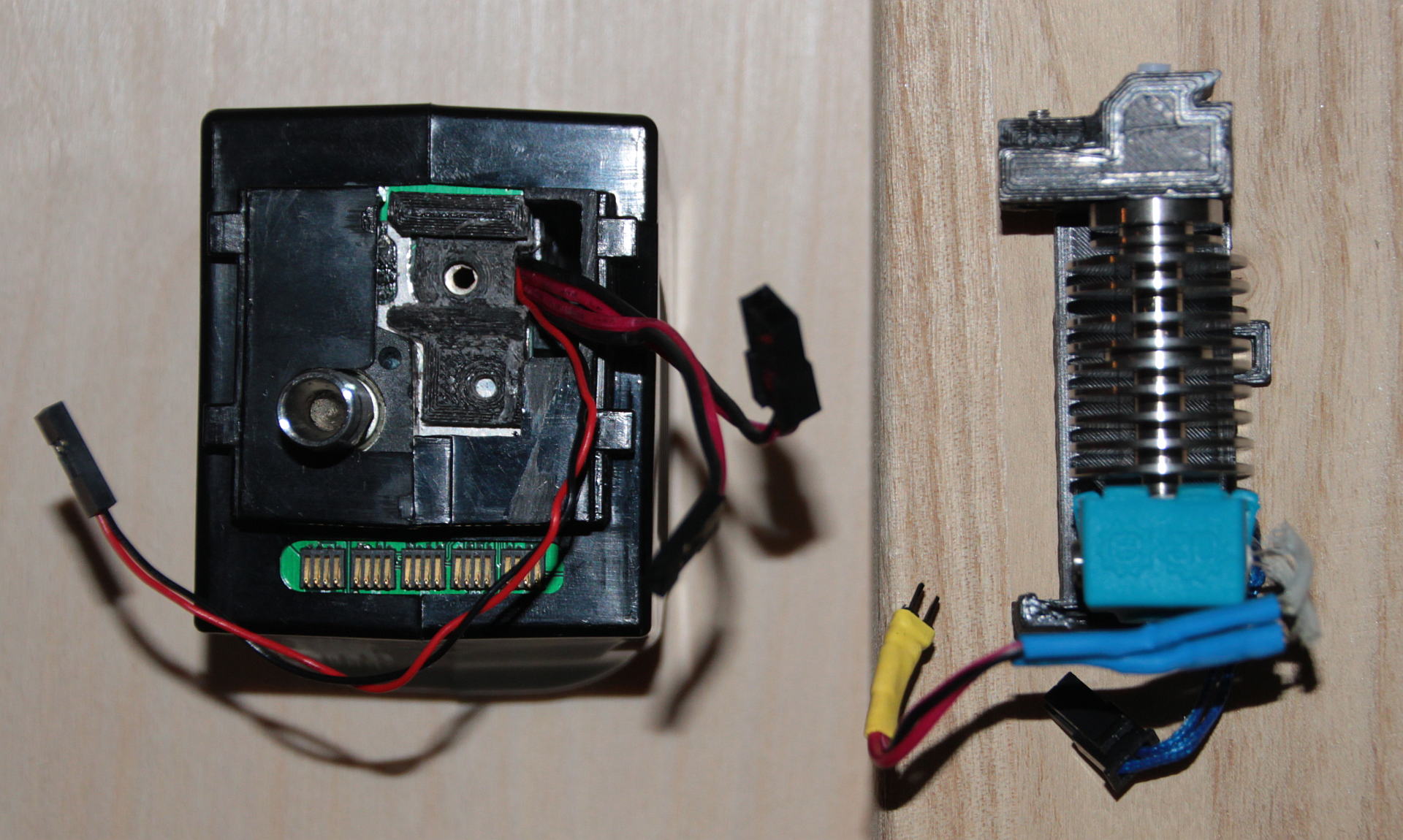
I finally scraped away the remaining glue, and here’s the result:
Software Changes
While waiting for the E3D delivery, I delved into the software, since the hotend comes with a different thermistor, which is not directly supported by Fabtotum. However, this can be mended easily.
FABlin/Marlin/Totumduino Firmware Changes
The Fabtotum controller board is dubbed Totumduino, basically an Arduino-ish Atmel MCU with Arduino bootloader, connected to a Raspberry Pi via serial port (which is why you always need the Arduino bootloader to have serial programming available). On it runs a Marlin clone, named FABlin. It is easy to modify and update the firmware, and it is nearly failsafe – in case something goes stupidly wrong, there is a plan B in form of a direct programming port (ISP) on the Totumduino board, which worst case allows a “low level” flashing of the MCU. So don’t be afraid of this step. If you want to be double careful, remove any head and the bed from the Fabtotum. A malfunctioning firmware might cause uncontrolled heating up of that components.
I got myself in trouble here – why and how I solved it I explain in the Appendix. I’d recommend that you read it to know what the worst case scenario might be, and to understand your risk. However, if you follow procedure, I’d say most likely it will not happen to you.
The firmware changes are necessary to enable and use the thermistor that E3D supplies with the hotend and mainly follow the E3D Marlin firmware guide. If you are hestiant to do software changes but still want to proceed, another option would be to fit the original Fabtotum thermistor into the new hotend. In my case the thermistor was just the naked glass blob, while the E3D needs a capsule. I guess it should be possible to replace the thermistor in the capsule, as in the capsule a thermistor of the same glass-blob-build is embedded. Its glass hovever, high likelihood to break something here. I also learned that later incarnations of the original hotend came with a thermistor capsule – so you may be just lucky. If so, you can skip all the software changes below (both firmware and FabUI) and use the original thermistor (if it fits).
Here’s the overview of all necessary steps:
- Download and install Arduino IDE (if you not already have it anyhow)
- Download/Clone FABlin master
- Make sure that all libraries are there
- Load Sketch
- Select correct board
- Make changes
- Compile (takes less than a minute!)
- Upload file to Fabtotum and flash it
- Control success
This is not the only possible procedure – look on the README.md of the FABlin repository if you’re interested, or look at the Opentotum version, which has an additional method using Docker. Opentotum is a second place the Fabtotum software and documentation is maintained.
In detail:
Download and Install Arduino IDE
Download the Arduino IDE matching your system. As of writing this post, current version is 1.8.10. In some pages you may find references that you should use an older version – I had no problems whatsoever with the current version. Run the installer – that’s it basically.
Download/Clone FABlin Master
It’s in a Github repository. Recommendation is to get your own Github account and do a fork, but I was too lazy and just downloaded as ZIP and unpacked everything in my home directory. When I did my mod’s, the version was 1.1.1.3.
Make Sure that All Libraries are There
More than one way to do this – if you want to know them, read the README.md in the FABlin repository. Here is what I did, since I already have Arduino IDE installed and use it for other projects also:
- Identify your Sketchbook location – For this go to the Arduino preferences:
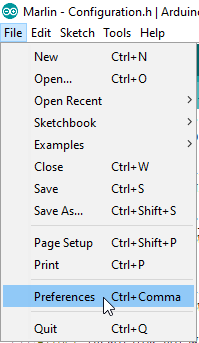
File > Preferences In the upcoming dialog you’ll find your Sketchbook location:
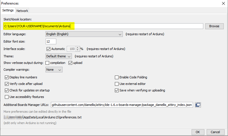
Find Sketchbook location - Go to <FABlin master directory>/libraries and copy the folder SmartComm into <Sketchbook-location>/libraries.
- Install the TMC2208Stepper library – For this use Tools > Manage Libraries…:
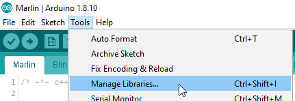
Manage libraries Then search for the TMC2208 library and select install:
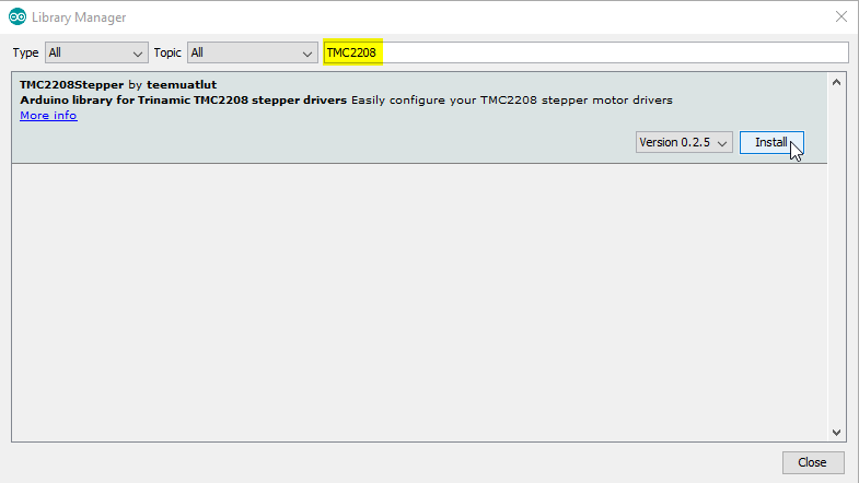
Install TMC2208Stepper Library
Libraries are complete now.
Load Sketch
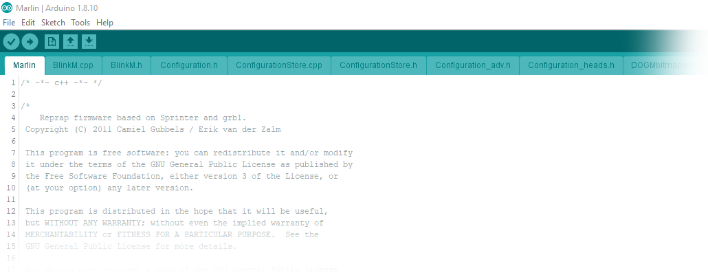
Navigate to <FABlin master directory>/Marlin and open the file Marlin.ino in the Arduino IDE (in Windows e.g. just doubleclick it). An Arduino IDE window should come up that has numerous tabs showing the source code.
Select the Correct Board
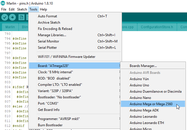
Arduino IDE needs to know which MCU it is supposed to compile the code for. The MCU used on the Totumduino is an ATmega 1280. So go to Tools > Board… and select Arduino Mega or Mega 2560:
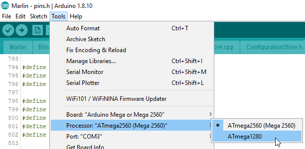
Then under Tools > Processor… choose ATmega 1280:
Make Changes
All necessary changes go into the file Configuration.h – locate the regarding tab and make the following changes (The line numbers I give were correct when I wrote this, i.e. version 1.1.1.3 – potentially they may change later, but the regarding sections should be easy to recognize. Honestly I expect the line numbers to be rather stable – since Fabtotum company ceased to exist there have been no changes to FABlin master branch any more.):
|
173 174 175 176 |
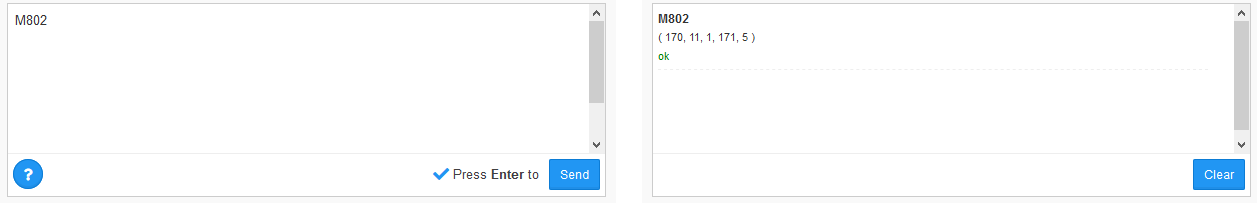
// USER CONFIGURATION: #define THERMISTOR_HOTSWAP_SUPPORTED_TYPES ( 170, 11, 1, 171, 5 ) #define THERMISTOR_HOTSWAP_SUPPORTED_TYPES_LEN 5 #define THERMISTOR_HOTSWAP_DEFAULT_INDEX 0 // the index of within the supported types to which the printer will be initialised. |
This adds the thermistor used by E3D (Semitec 104GT) to the supported ones – Marlin knows about it (the number 5), but FABlin had it disabled. The length of the array goes to 5, hence the change of the next line.
Some people suggest also to change the default index to 4 (selecting the Semitec as default), but I was reluctant, since I am not sure if this would not also affect the thermistor of the heated bed. I found a different way to change the default for the new head alone – stay tuned…
Another change to Configuration.h:
|
250 251 252 253 254 255 |
// When temperature exceeds max temp, your heater will be switched off. // This feature exists to protect your hotend from overheating accidentally, but *NOT* from thermistor short/failure! // You should use MINTEMP for thermistor short/failure protection. #define HEATER_1_MAXTEMP 245 #define HEATER_2_MAXTEMP 245 #define BED_MAXTEMP 110 |
The E3D Lite6 can stand slightly higher temperatures than the original Fabtotum hotend. So the overheat stop will come later… N.b.: Later in the whole process I realized that this setting is potentially ignored: The device derives the overheat limit from the maximum head temperature + 15°C – will refer to this later.
If you use the E3D V6, adjust this line to the even higher temperature that hotend allows for.
I did not change in Configuration.h (yet?):
|
141 142 143 |
#define TEMP_SENSOR_1 0 #define TEMP_SENSOR_2 0 #define TEMP_SENSOR_BED 1 |
It seems not neccessary – but I’ll monitor behaviour of the printer closely and may change the 0 to 5 later. The E3D Marlin page suggests it. Still, as far as I understand it, my other modifications later in this post should make it unneccessary to change the value.
Optionally, but recommended, finally make the following (or similar) changes to Configure.h:
|
15 16 17 18 19 20 |
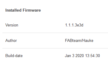
// User-specified version info of this build to display in [Pronterface, etc] terminal window during // startup. Implementation of an idea by Prof Braino to inform user that any changes made to this // build by the user have been successfully uploaded into firmware. #define STRING_BUILD_VERSION "V 1.1.1.3e3d" #define STRING_BUILD_DATE __DATE__ " " __TIME__ // build date and time #define STRING_CONFIG_H_AUTHOR "FABteam/Hauke" // Who made the changes. |
This allows you later to verify successful flashing of the firmware.
No other FABlin changes requried, you can now
Compile
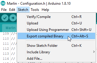
I use the menu item Sketch > Export compiled Binary since it directly creates the required firmware file:
If you did everything right, after 10 seconds or so in the lower window part you should see a message like this:
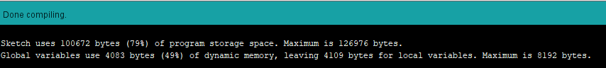
If you see orange messages – well, something went wrong. Read the messages and figure it out!
Now navigate to <FABlin master directory>/Marlin and locate the file Marlin.ino.mega.hex. Make sure to pick the one without bootloader! There is a second hex file with bootloader – using this would make plan B necessary, since the then two bootloaders mess up everything. And for plan B you’d need an AVR programmer – save the cost and use the right file 🙂
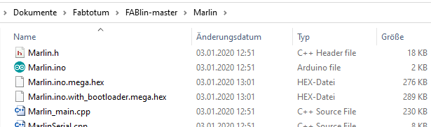
I personally copy the file somwhere else to make finding it easier later, and I shorten the name, e.g. to Marlin.e3d.hex.
Upload File to Fabtotum and Flash it
This hex file now needs to be uploaded and flashed to the Totumduino, which is easy using the FabUI (aka. the web interface of Fabtotum). Navigate to Maintenance > Firmware and choose Upload custom from the picklist. There will be a button to select the file to upload – but funny enough it does not work when clicking. What you need to do is click somewhere at the border of the grey area – I highlighted the “valid” areas in yellow in the image below:
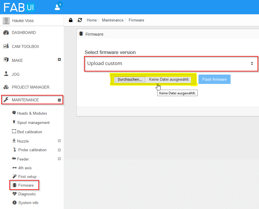
After selecting the hex file from the previous step, click Flash firmware. The LEDs of the Fabtotum will go dark, the update will commence, it beeps and the lights flash greenish.
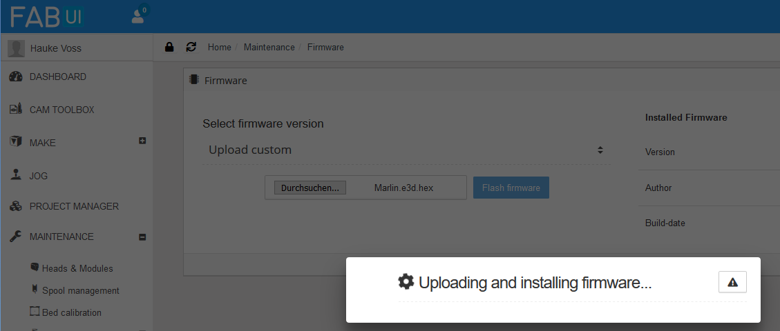
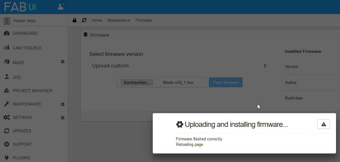
The firmware update takes about one minute, then you’ll be notified about the successful update and the controller reboots, lights turn white again.
Control Success
To control if everything went smoothly, go back into FabUI and navigate to Maintenance > Firmware – you now should see version and author as put into Configuration.h:
Now lets check if the other settings were accepted. For this go to the Jog page and issue the G-Code command M802, which gives the list of available thermistors – now there are five, including the new number 5:
I first thought that M801 gives the minimum and maximum temperature from the firmware, as it shows 245°C, but it turns out that this value is calculated from the maximum temperature of the head, which is changed later in the process.
You could also do M765 which would give you the firmware version, but we saw this already in the UI itself.
In addition I did some more tests, like jogging the head a bit, homing all axes, setting a bed temperature and see that this works, letting the milling motor spin, switch fan on and off and also re-attached the old heater block with heater cartridge and thermistor to check that controlling those works. All was fine.
Success! FABlin is ready for E3D!
FabUI Changes
As I continue to use the board and hardware of the hybrid head with the exception of the thermistor and hotend, I wanted also to use the existing hybrid head configuration profile. So what I needed was the possibility to select the now firmware enabled thermistor index 4 from the thermistor dropdown in the advanced head settings. With a few changes to the FabUI this is possible. My modifications are based on FabUI Colibri 1.1.6.
If you don’t want to meddle with the FabUI, I guess you have two options (which I both did not test, so try it out yourself):
- In the Custom initialization section of the hybrid head include the following G-Code:
M800 S4
This sets the thermistor index to 4. What you’d need to test: Is this overwritten by the thermistor setting in the profile at a later point? The thermistor selected in the profile basically ends up in a M800 command, and the question is what comes first: the custom init or the profile init? - In the Configuration.h also change lines 141/142 (TEMP_SENSOR_x – x = 1 or 2) to have value 4. This changes the default index. To be tested: is this overwritten later by the profile? I’d suppose yes. So most likely this won’t work.
Since the FabUI changes are easy, I’d recommend to follow me here.
To make the changes, I just SSH’d into the Raspberry Pi of the Fabtotum – use your favourite SSH client and go in via the IP of the Fabtotum. Login is root, and no password is required. I once set a root password, but Fabtotum just resets it to empty… I don’t like, but did not yet try to fix this.
I guess again it would be more proper to fork in Github and update FabUI the proper way, but I didn’t bother.
The line numbers again refer to the line numbers when writing this post (i.e. version 1.1.6) – may have changed in the meantime.
Changes to /var/www/fabui/application/controllers/Head.php
In the $data[‘thermistors’] array an entry has to be added (note the added comma in the line above!):
|
180 181 182 183 184 |
$data['thermistors'] = array( '0' => 'Fabtotum', '1' => 'Standard 100k', '4' => 'E3D Semitec 104GT' ); |
Changes to /var/www/fabui/application/views/head/install.php
In here we add the option to the UI dropdown:
|
255 256 257 258 259 260 261 262 263 |
<section class="col col-6 advanced-settings"> <label class="label"><?php echo _("Thermistor");?></label> <label class="select"> <select id="head-thermistor_index" name="thermistor_index"> <option value="0">Fabtotum</option> <option value="1">Standard 100k</option> <option value="4">E3D Semitec 104GT</option> </select> <i></i> </label> </section> |
Results and Control Success
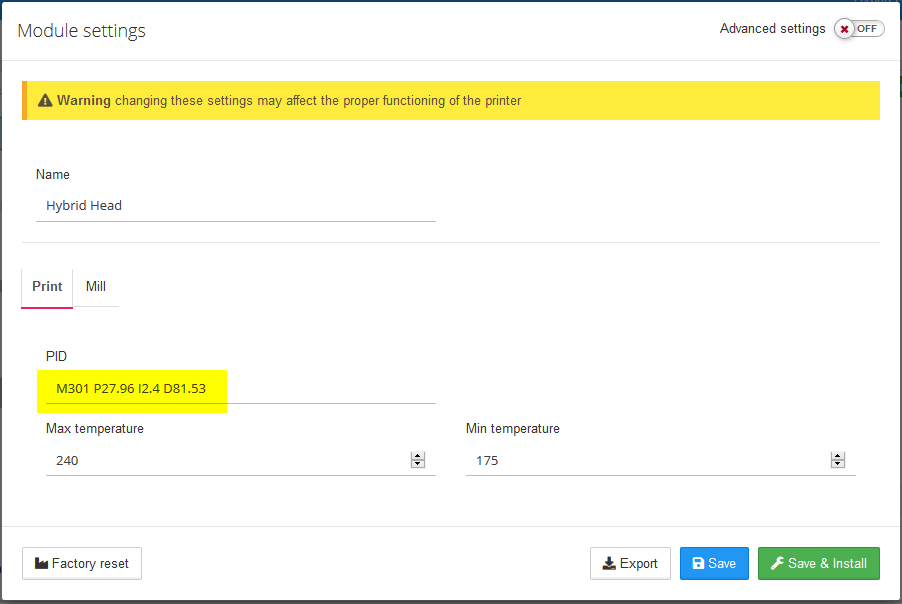
With above changes, I now can select the thermistor in the head setup. To get there, in FabUI choose Maintenance > Heads & Modules and select the settings for the Hybrid Head:
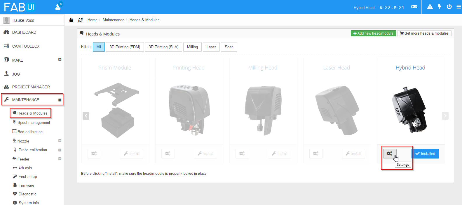
You need then to switch Advanced settings on:
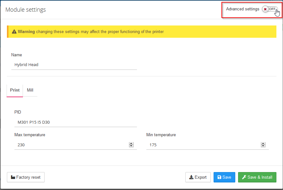
Now you can pick the correct thermistor. Also set the new max. temperature – the E3D Lite6 can get a bit higher than the original hotend. If you have the V6, set the correct value for it here. Side effect: The overheat protection temperature seems to be hard coded to max. temperature + 15°C – After you changed the value here, M801 command will return a different value than before.
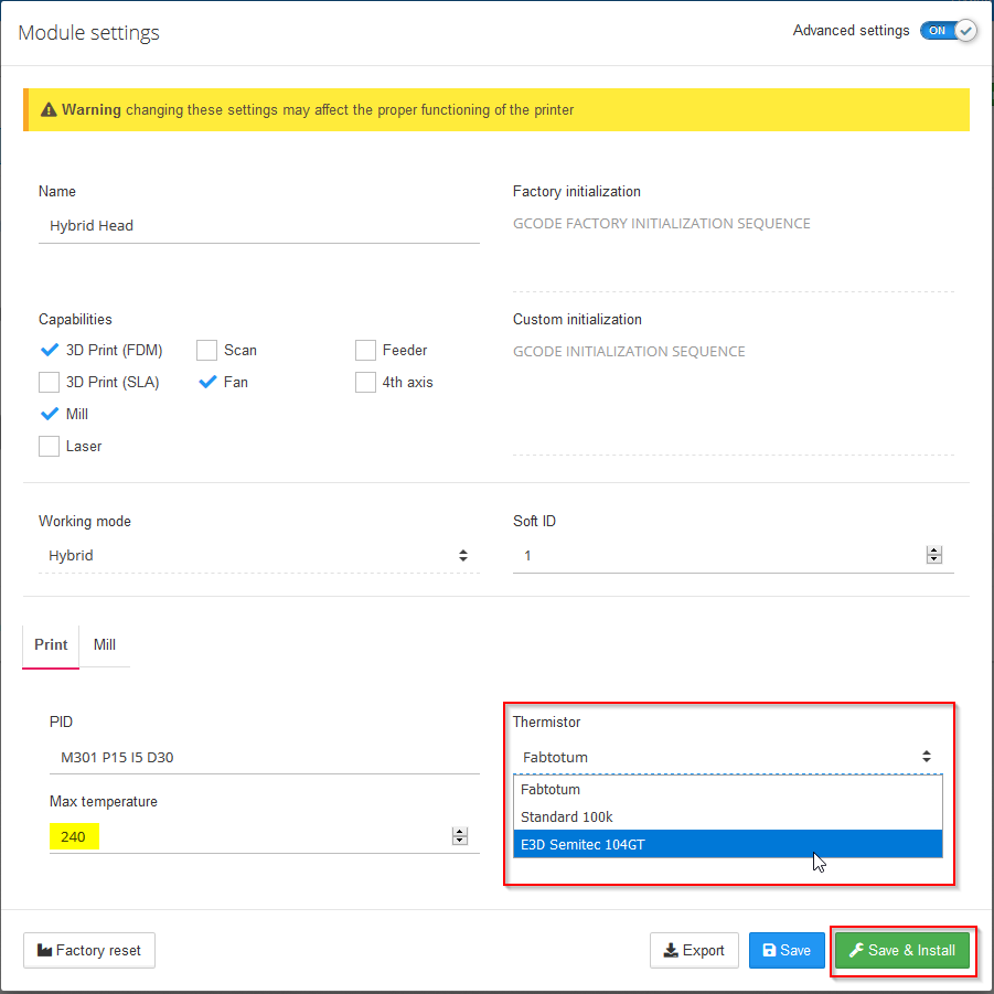
Click Save & Install to let the changes take effect.
To check the success of this, go to the Jog section and enter G-Code M800:
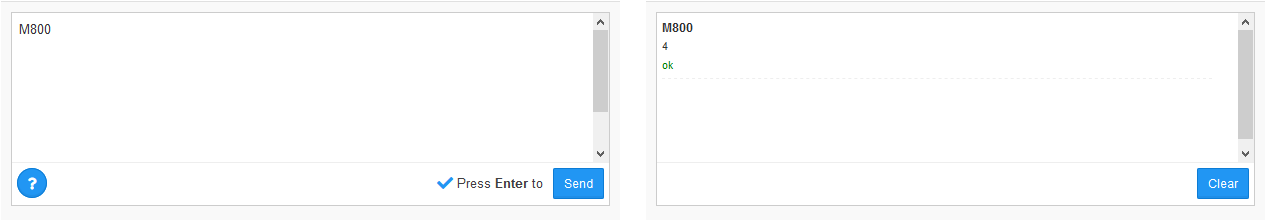
You will now get the value 4 as result – Success!
Please be aware of two things:
There is a “bug” in the FabUI: When you later open the head settings, the thermistor will always show as “Fabtotum”, regardless what you selected beforehand. In case you later make other changes to the head settings via FabUI, always make sure that you set the thermistor right again.
Second thing: All settings go into the file /mnt/userdata/heads/hybrid_head.json on the Raspberry. I played around a bit with it and had the idea to change the name of the head in there. This confuses the printer considerably, since name of the head and filename need to match. In other words, if you want to change the name, also change the filename. Also then create an image with the name that is displayed in the head selection window. It may be more complicated – I just started to understand the intricacies, but I could not care less, so I changed name and filename back to hybrid head, and stopped there.
(Potentially Optional) Changes to /var/www/fabui/ext/py/fabtotum/fabui/macros/calibration.py
After putting in the hotend provisionally it became clear that there is too little space! See the photos in the next section – you’ll understand what I mean. Only solution: The hotend must go deeper, sacrificing vertical build volume. Aside from that, another concern was that when running the assisted nozzle height calibration, the printbed might run into the now longer hotend, which for obvious reasons would be bad. To avoid this, furtunatly just the python macro that takes care of the calibration process needs one modification. I first could not find it, but with the help of Christopher Witmer from the Facebook Fabtotum group I was able to find the code and locate the line – Thanks! In the end my hotend did not protrude as deep as I was afraid of, so I might have skipped the modification, but to be on the safe side I changed it at leat a bit:
|
99 100 101 |
# Move closer to nozzle app.macro("G90", "ok", 2, _("Setting abs position"), verbose=False) app.macro("G0 X103 Y119.5 Z30 F1000", "ok", 100, _("Moving the bed 30mm away from nozzle"), verbose=False) |
I double checked that this is enough: I did a height calibration and then an empty fake print without hotend to be sure that the calibration is used correctly in the print, which it is.
From looking around for the code I learned that the nozzle calibration goes into nozzle_offset in the head JSON file in /mnt/userdata/heads.
Getting In the New Hotend
Removing the Obstructing Part of the Base Plate
I would really have loved to skip this step, since the dimensions of the hole with 12 mm width would have been perfect to insert the E3D hotend into! However, despite trying hard I was not able to disassemble the unit to get the plate free. So in the end I took a metal saw and sawed the obstructing part away, now having a U-shaped gap to put the E3D into:

Be sure to clean away all metal shavings from the PCB!
(Optional) Fitting in the E3D – Temporary Solution
You can skip this step if you have access to another 3D printer and do the proper mounting later – for the proper mounting you’ll need to print a few parts. I don’t have another printer, so I first mounted the hotend provisionally to make my prints. (Please note, I do not recommend to do this – see my remarks at the end of this post)
The new hotend fits nicely in the U-shaped gap, but the rift is too broad so that the hotend is not constrained well vertically. I went for some rubber seals for cables, and cut one to fill the gap.
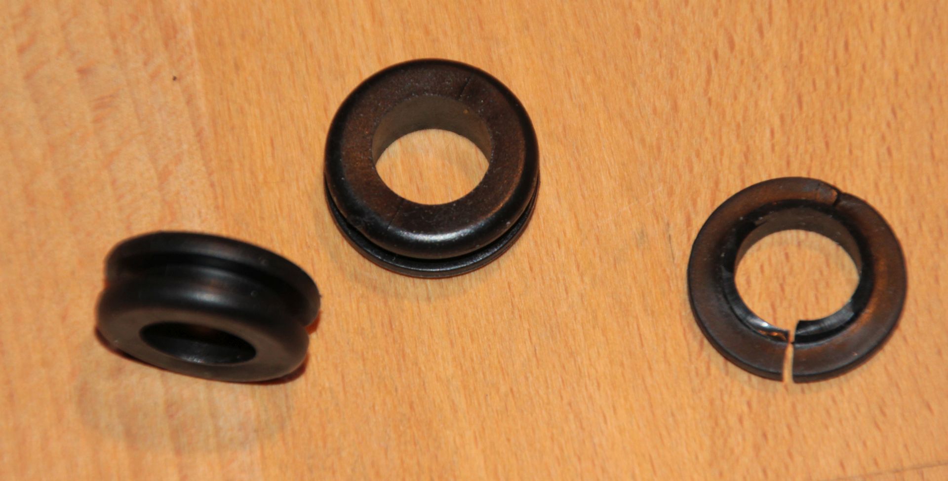
It also insulates the PCB from the metal hotend. This was already enough to fixate the hotend snugly:
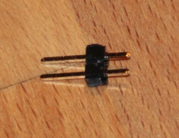
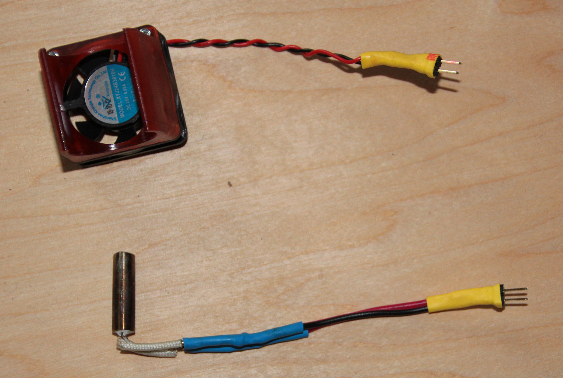
To connect the thermistor, I used a two pin jumper connector, which is not perfect, but good enough:
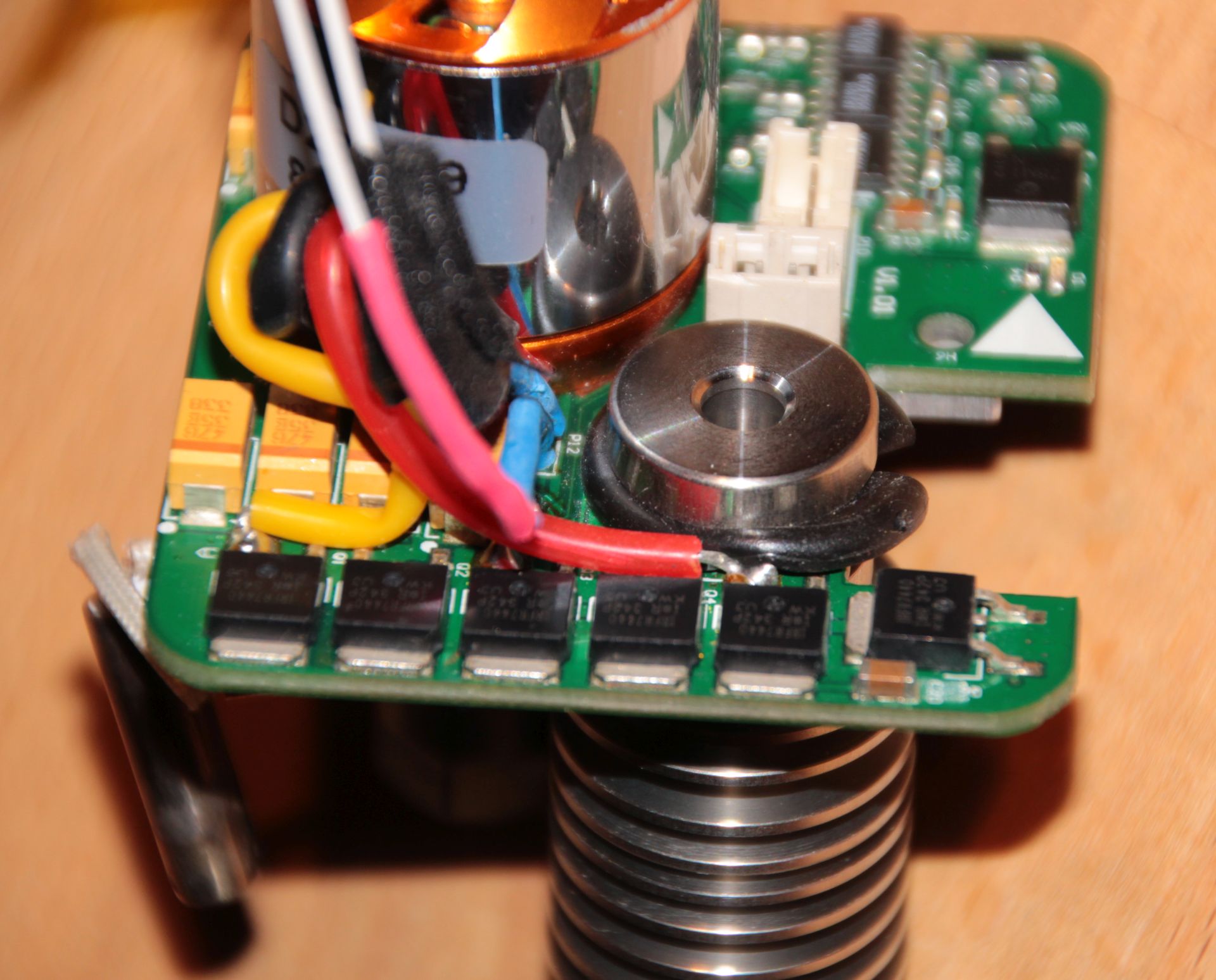
For the provisional mount I used the old heater cartridge – mainly because I was yet unsure how the cables would later run:
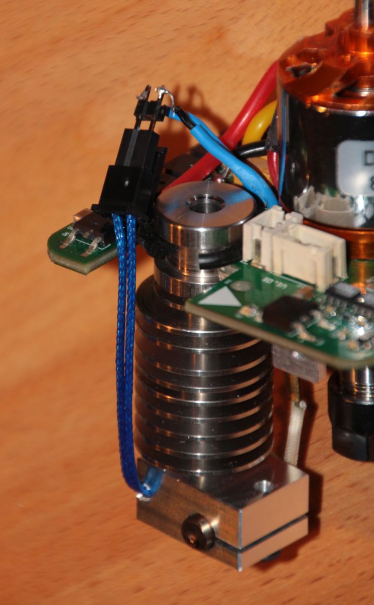
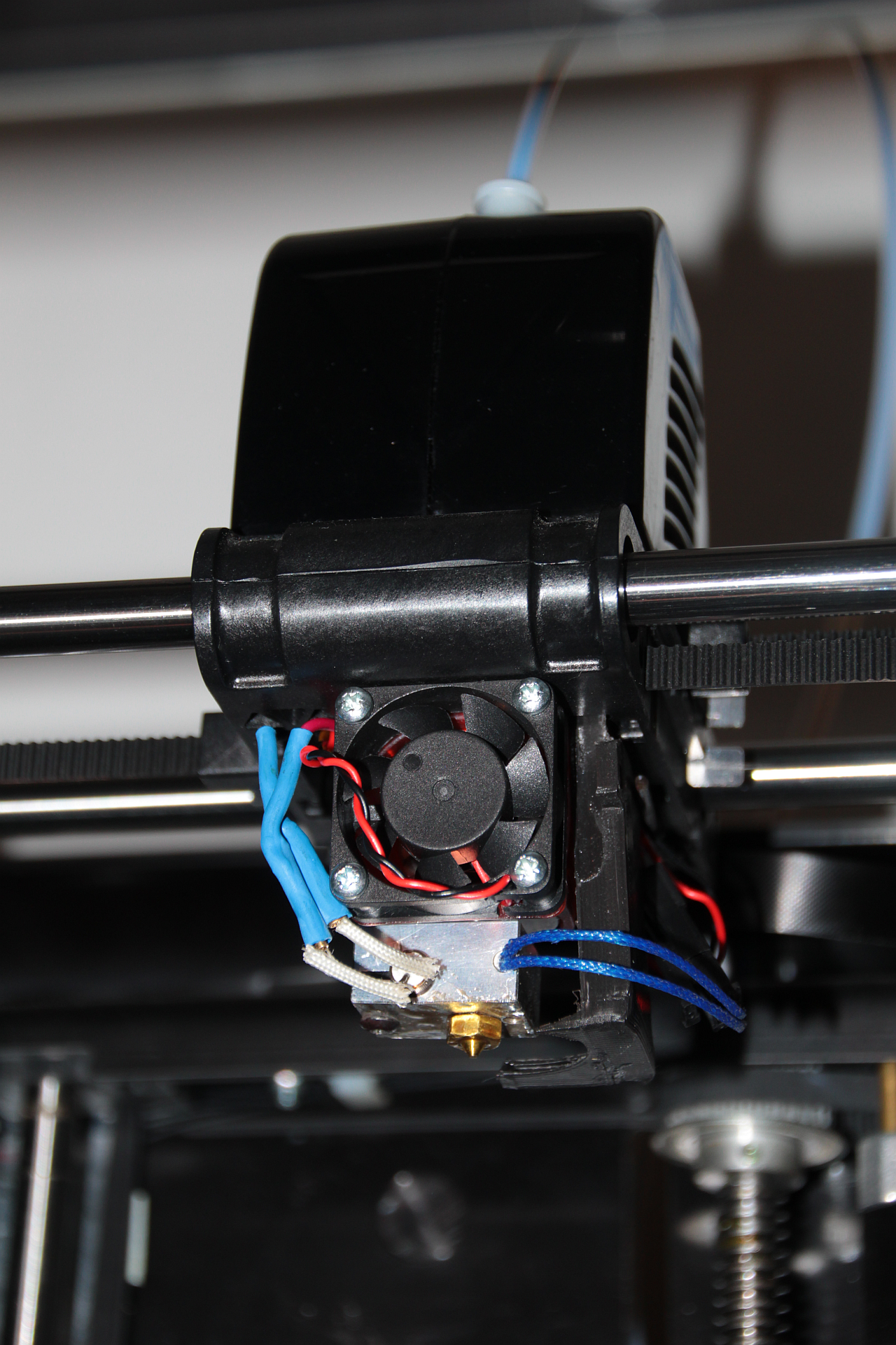
Things are really tight now!

Putting the head together, it is even worse (I did not yet screw the head together in the photos – the gap in the head housing looks worse as it is):
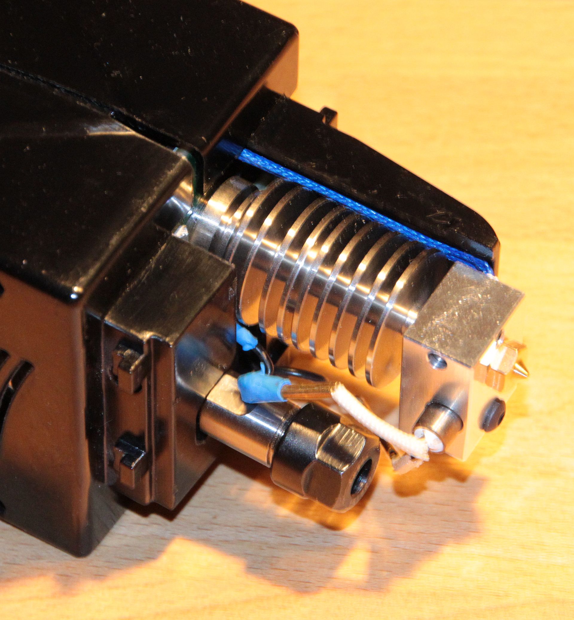
Still, I was a bit stupid here – rotating the hotend by 90° would have made it a bit less problematic, as you can see here.
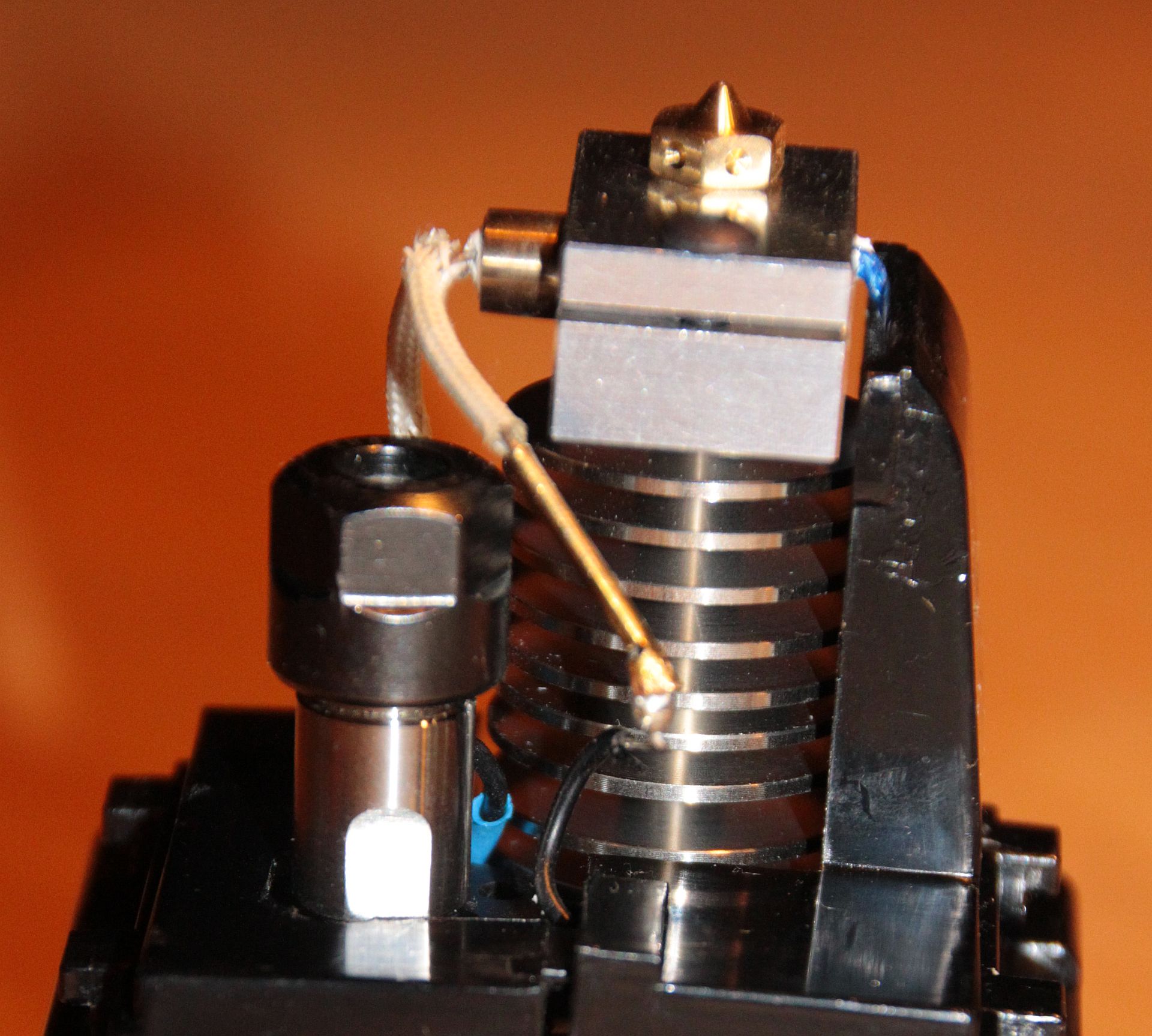
And the head mount adds to the problem:
So, the E3D fan does not fit in. But the fan in the head does not put its full power on the heat brake – I decided that this must be enough and give it a go! The only thing you need to remember in this setup to always switch on the fan via Jog page whenever the heater is on to provide cooling to the heat brake.
I now followed the remaining steps in the E3D Assembly Guide. In there I learned for the first time in my 3D printing life of
PID Tuning
and that is very good! And with Fabtotum surprisingly easy!
PID tuning is an automated process in which the printer establishes the thermodynamic paramters of the hotend in order to keep head temperature as stable as possible. For this, it does a number of heat/cool cycles and measures how temperature develops over time. In FabUI navigate to Maintenance > PID tune and select Start (did already in the screenshot, now says Abort):

Wait a few minutes, then save:
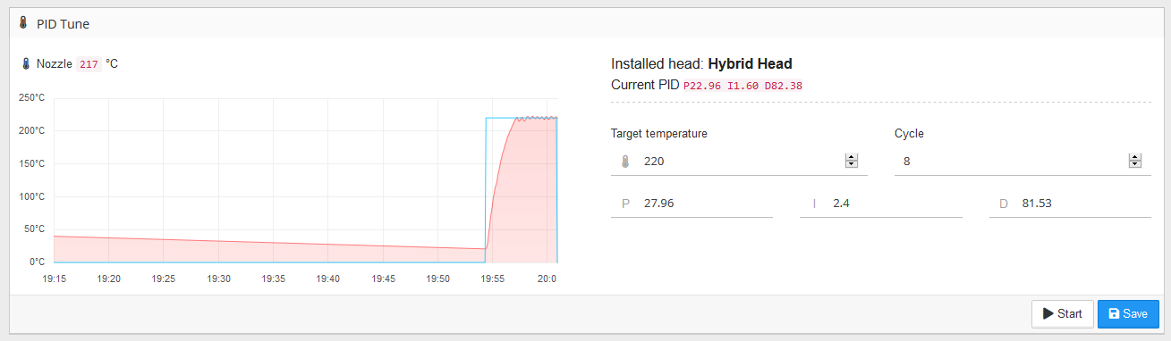
You can see the temperature wiggles getting smaller! The PID tune values go into the head configuration:
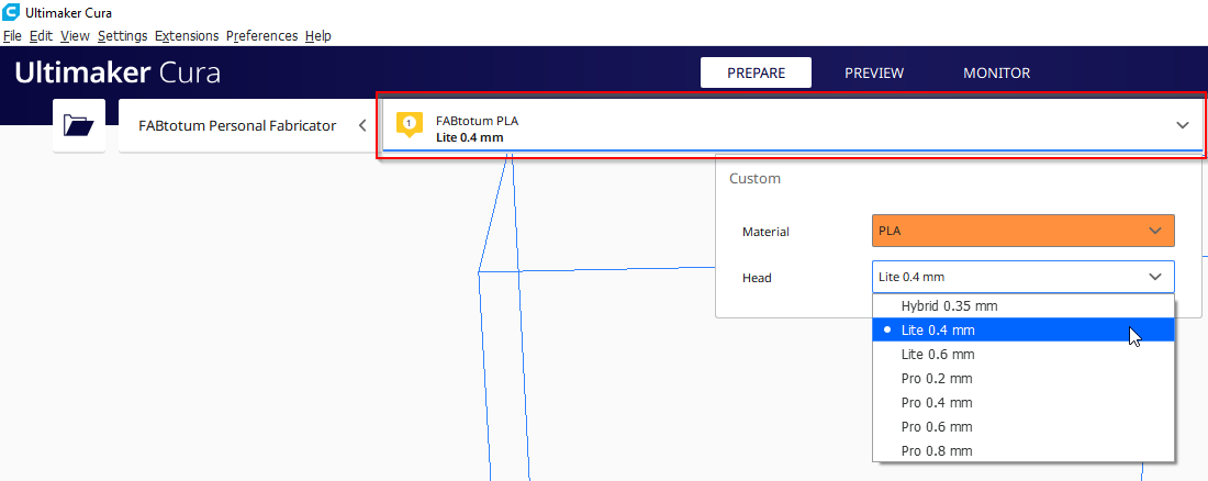
Change Nozzle in Cura
In Cura there are already profiles for different nozzle diameters, so that was easy – just pick it directly from the UI:
Back in Business!
Time to start the first print! First of course nozzle height calibration, but off we go! I struggled a bit with bed adhesion in the beginning, but after a few fine tunings I was up and running:
First print with the E3D in place!
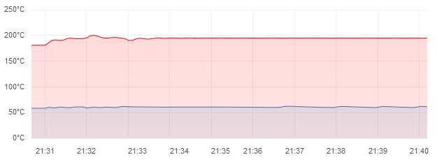
Print result was already very good, despite of missing print cooling fan.
And here the effects of PID tuning were to be seen – the temperature stayed on spot for the whole print! Before, with default values, temperature was oscillating by a few degrees!
Actually, if you do not need print cooling, you’re basically done now – let me again mention this page: It kind of stops here, but they removed the milling motor, which gives a bit more space. I suppose, milling functionality would still be given with my mod, but I never tried.
Parts for Final Mounting
Please note: I do not recommend to follow me through the rest of this. I think the basic idea is sound, but you lose considerably in vertical build volume and everything is a really tight fit. It works, but as mentioned before, I decided to go for a separate print head – blog post on this to follow. My starting point will be this thing on Thingiverse.
After preliminary mount it was clear that the hotend needs to go a bit lower to allow for the E3D clip-on fan to be somewhere and to avoid collisions between the heat sink and the milling motor bearing. Still, I wanted to be able to use the milling functionality. Admittedly, I most likely will not use it, since my first steps into it left me with the feeling that Fabtotum is not robust and powerful enough to do milling, but still, you never know. With the hotend sticking out further, the only solution could be that the hotend needs to be removable with acceptable effort. So my general design criteria were:
- Needs to fit into the existing head
- All parts including the clip-on fan need to fit in
- Hotend needs to be removable (for milling) without dismanteling the whole head
- I wanted to be able to pull the bowden tube from the head as with the old hotend – the E3D hotend itself makes this difficult
- The old head was bad at overhangs – so I wanted to improve the print cooling
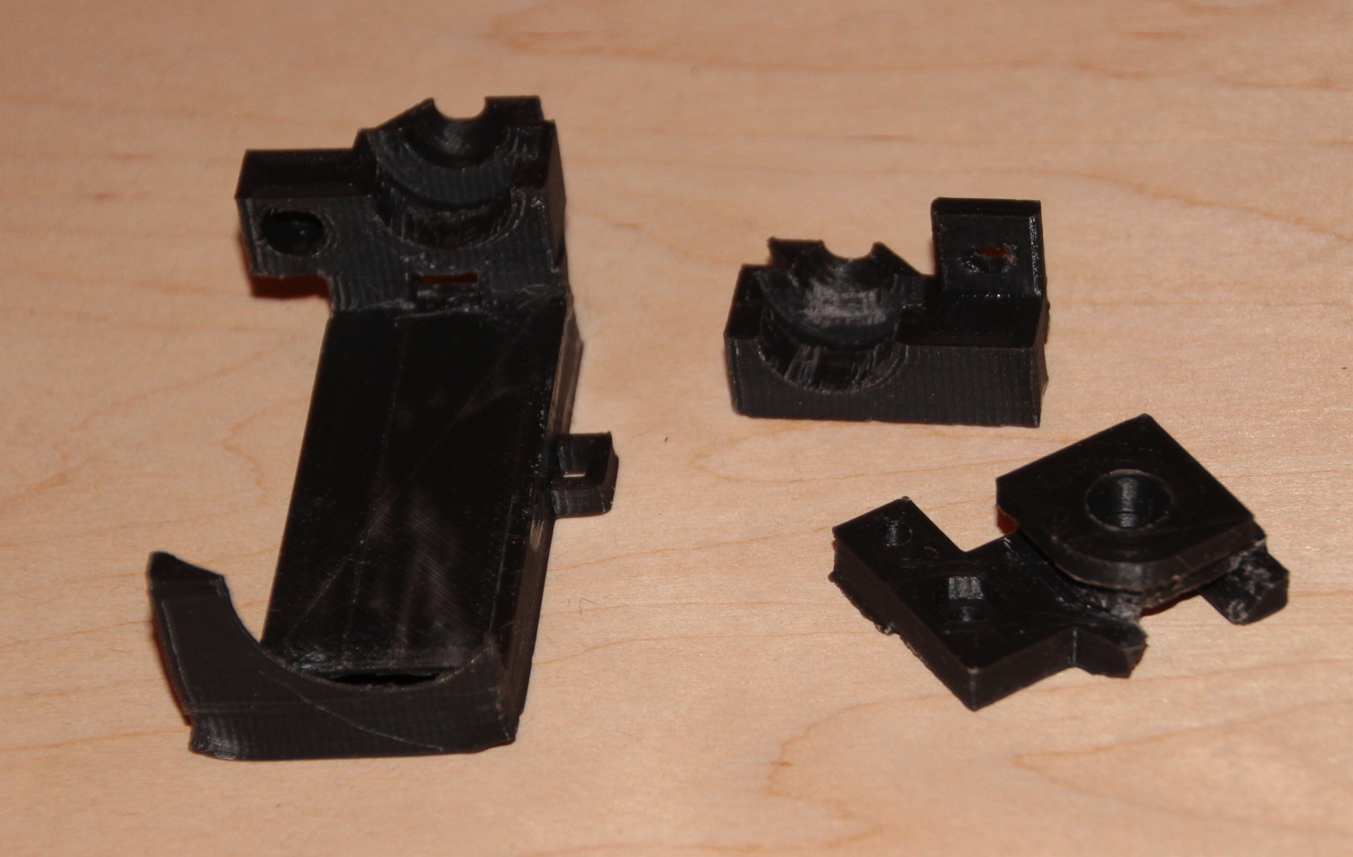
Here’s what came out (dark green/gray/white/black: PCB, metal part and obstructing jacks and bearing; yellow/white/red/orange: hot end and PFTE tube; purple: new part to go into the U-shaped gap permanently; olive/light green: two-part hotend carrier with air guide and screw-mount/dismount option):
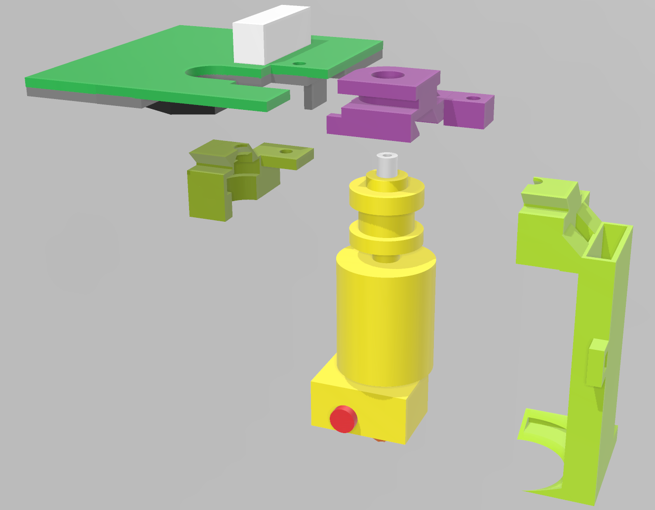
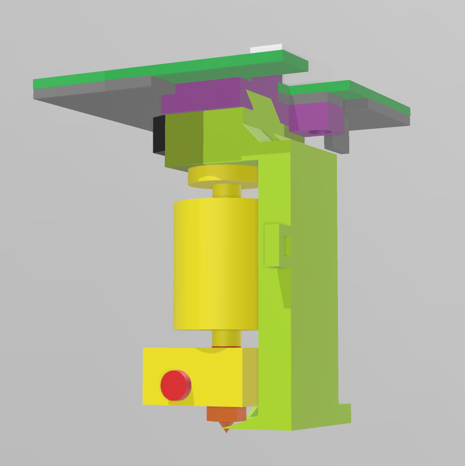
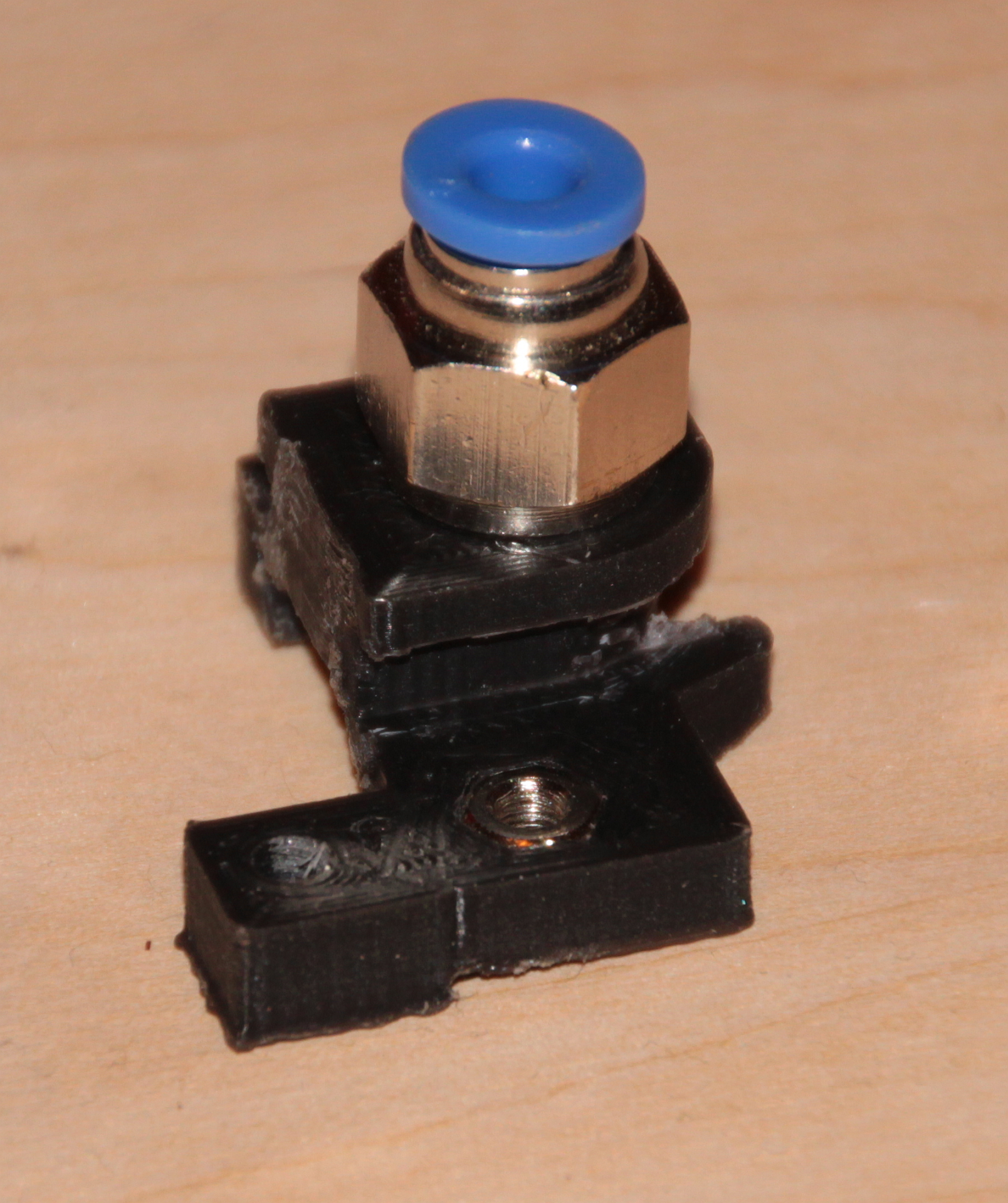
My apporach is a fixed mounting plate that goes into the head. Into this, I screw the old bowden coupling from the old hotend. This allows me to pull the bowden tube like before. The hotend is put between two carrier parts, that snap into the aforementioned mounting plate and are fixed then by one screw. I also created an air guide for better cooling – let’s see how it performs. The air guide will be fed by the blower fan in the head, which in the original configuration seemed to have a mixed job: Cooling both the heat brake and the print. Since E3D provides a dedicated heat brake fan, I decided to only use the blower for print cooling – with a small exception in form of a gap where the air duct is connected to the mounting block: I bit of air should go through there, since I am a slightly concerned that the air duct may get too hot from the closeby hotend otherwise.
Small detail: The air guide has a notch to fix a zip tie to for cable organization.
To mount everything, you need two M3 × 12mm screws with matching nuts. Put one nut into the mounting plate before sliding it into the PCB. Use one screw/nut to fix the mounting plate using the existing hole in the PCB/metal part. Clip together the carrier parts around the E3D hotend top, slide it into the mounting plate and use the second screw to fix it tight.
I printed the parts with the provisional setup, and they came out just fine, with quite a bit of stringing. I used 100% infill for stability, and support everywhere – especially since I had no print cooling in place. Support removal was a bit of fiddely work, but came out well in the end. A bit of damage done when getting the support out of the airguide – which involved the careful use of a 3.5 mm drill, a flat craft knive and a long, thin screwdriver. A bit of superglue fixed the damage easily *phew*.
The part files can be downloaded here.
Removing the Old Air Guide
For everything new something old must go… In this case the bit of plastic of the head shell that worked as an air guide before:
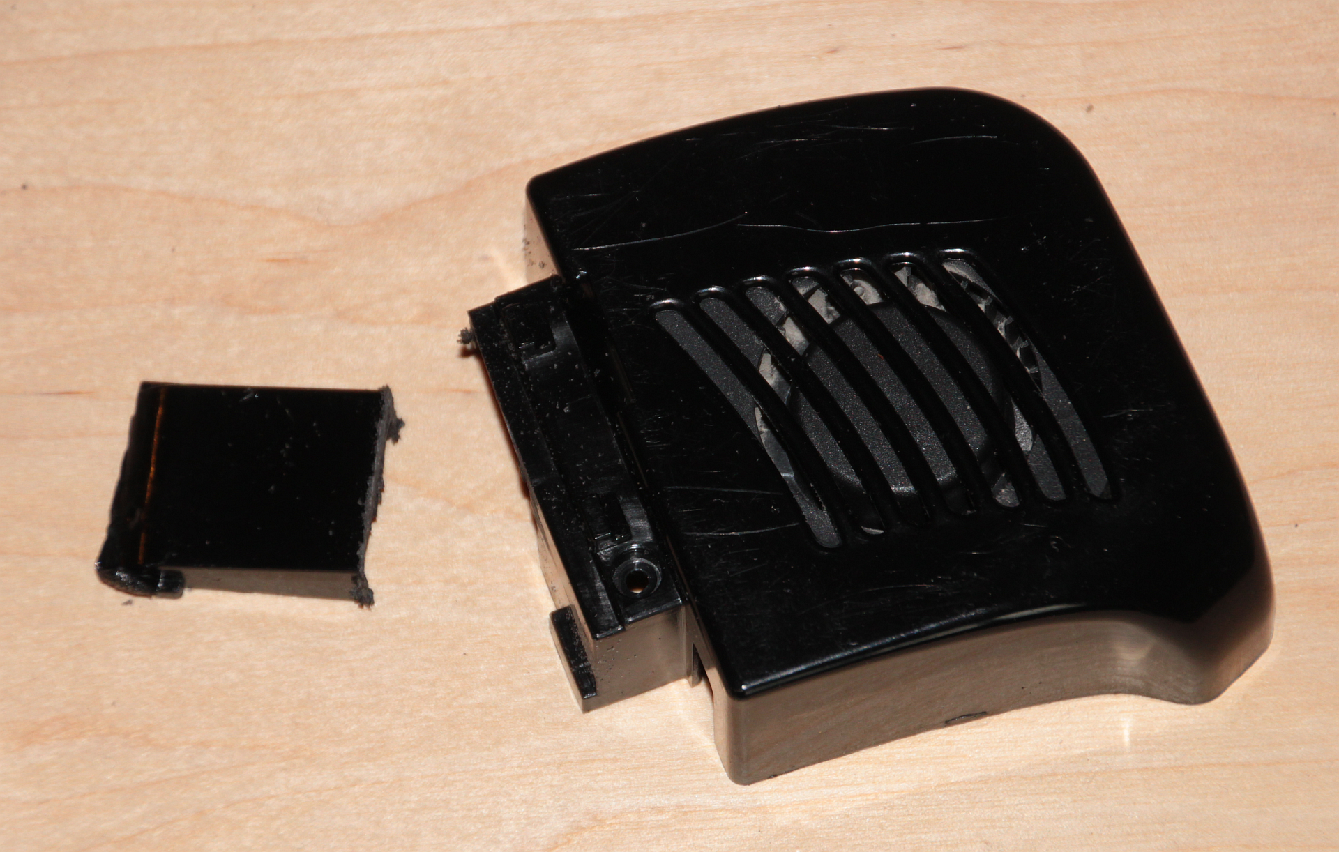
Also, a small piece of plastic of the underside needs to go to make place for the mounting parts:
Parts Printed and Mounted
Everything becomes reality:

I had to cut away some of the new air guide – I did not take the head mount of the printer into account properly.
Did I mention that it really is a tight fit?
Controlling the New Fan
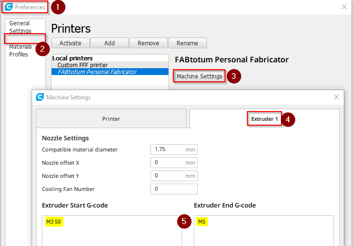
The 24 V fan for the heat brake that comes with the E3D heads can be controlled via the 24 V head voltage G-Code. With M720 it is switched on, with M721 it is switched off. In the hybrid head the 24 V also drive the milling motor, and the implementation has it that issuing M720 also lets the head do the beep-beep-beep cascade that you may know from the milling startup sequence or when using Jog to spin up the milling motor. In addition, it seems that the code in the hybrid head is somewhat weird – after several seconds the motor does another beep, and after two minutes or so it starts the motor – just so. No idea why… In the end I went for an alternative method: I used M3 S0 G-Code, which is “Motor on clockwise, 0 RPM”. To switch it off, it is just M5. I included this in the Cura Extruder profile:
After running some prints, I noticed a strange behaviour: after about 15 minutes the print head starts to emit regular beeps, created by the milling motor (It is always funny to see how they use the motor for making sounds!). Obviously the head’s MCU complains about having 24 V on, but not using the motor. This is really annoying, having your printer beeping all the time while your print runs! Of course, you can pause the print, send M5 and then M3 S0 again for another 15 min’s of silence, but really?
Update on Beeping
Again Christopher Witmer from the Facebook Fabtotum group was helpful here: He pointed me on the firmware for the milling head, which can be found on Opentotum. As it turns out, it is based on code written for controlling drone motors, and in the source code there is the routine that does the beeping – the comment tells what its intention is:
|
2998 2999 3000 |
;-----bko----------------------------------------------------------------- ; If we were unable to start for a long time, just sit and beep unless ; input goes back to no power. This might help us get found if crashed. |
It is to locate a crashed drone… Well, I’m sure my Fabtotum will not fly away 🙂 Anyhow, I do not plan to go deeper in modifying the head software – it is in assembler language and I’d need to learn a lot, for limited gain. For the remaining prints, I’ll just detach the motor electronically, and reattach it when I am done printing.
At This Point I Stopped!
So, here I decided to stop and switch tactics to build a dedicated print head based on this Thing. With where I am I have the following problems:
- Beeping. Solution: Change the ATMEL MCU code in the print head. Problem: I cannot find the original source code for modification. Alternatively exchange the 24 V fan for a 5 V fan put in parallel to the blower fan – supposedly much easier.
- The bed probe is obstructed by my air guide. Solution: Modify the self-made head mount.
- The air guide did not fit well and needed some cutting, making it inefficient. Solution: Change air guide.
- Stability. My design is OK, but improvement for a better clamping of the head would be possible. Also, I might change for a bayonet coupling, since sliding in the PFTE tube is tricky with the current setup.
- The clip on fan just barely fits in. Solution: Modify the mount to have the hotend another ~4 mm lower.
- Loss in vertical build volume. With the 4 mm to be added, I’d be somewhere 2.5 – 3 cm short of before. Solution: None, impact: Acceptable…
- Cable management: My current mount has problems getting all cabels properly out of the head. Solution: Change the mount, but it is not as easy as it sounds, since there is not much space after all.
Being generally frustrated by how tight and unwieldy everything is, I decided to stop here. I’ll keep you updated as soon as I have built my dedicated print head!
Still, it works:
“Final” setup up and running
That’s it for now – I’d call it a success, but not good enough after all. Still helped me to understand the Fabtotum much better. And I must say that FabUI is really a good interface – it’s a pity the company did not make it, I think there would have been much to expect from them!
Appendix: Broken Bootloader
After flashing the firmware the first time, suddenly I could not do it again via FabUI. The UI just got stuck during the process. The LED lights went dark only very shortly, then came back flashing green-ish, and nothing happened. Powercycling showed that the new firmware was not flashed.
So digging a bit deeper, on the Raspberry there is a log: /var/log/fabui/avrdude.log – in there were tons of unhappy error messages like those:
avrdude-original: stk500_getsync() attempt 1 of 10: not in sync: resp=0x65
avrdude-original: stk500_recv(): programmer is not responding
avrdude-original: stk500_paged_write(): (a) protocol error, expect=0x14, resp=0x03
Still, using avrdude to read from the Totumduino worked, so in general connection was there.
I found this page, but the suggested solutions did not help.
In the end I think the following happened, reading this post on Stackexchange: I thought I’d always need to use the hex file with bootloader, but the bootloader itself takes care that it is not overwritten while flashing, so I ended up with two bootloaders on the chip, which may interfere with each other in an unfortunate way. I tried to reproduce this by once again uploading a firmware with bootloader, but this time nothing broke. My explanation: First time I had two different bootloaders, the old from the time the Fabtotum was built, and the new one I uploaded, and these clashed. The second try I uploaded two identical bootloaders, which use the same memory addresses, commands etc. – so regardless which one is currently active, they work consistently together. Still, I may be wrong here, so there is a slight risk that something else might cause bootloader curruption.
In which case you need to do plan B (the author had a similar problem with a corrupted bootloader), although I did it slightly different. Important: The plan B procedure I just linked in misses the step of backing up and restoring the EEPROM – which does not seem to be a huge thing, but I still recommend to do that step.
The way I did it avoids all the hassle with unmounting fans and the Raspberry. For this you need an AVR programmer that can separate its own power from the Totumduino power (I e.g. own a Diamex All-AVR programmer that can do this), which allows you to have the circuit powered from the Fabtotum PSU instead through USB (which is unable to deliver enough power).
Here’s my procedure:
- Open the left Fabtotum side where the Totumduino board is (Warning: This means that mains voltage is exposed around the power plug/switch and at the PSU terminals! Be sure that you know what you are doing, and do it at your own risk! Don’t touch mains voltage at any time! If you are unsure, disconnect power from the printer, unmount the Totumduino board and program it outside the printer or follow the plan B document, but include the EEPROM stuff below.)
- Connect the programmer to the ISP in the right orientation (see plan B document for photos!)
- Switch on Fabtotum
- Log in (SSH) to Raspberry Pi
- Do a ps -ef | grep py – will yield output like this:
1226 root 0:03 python /usr/share/fabui/ext/py//FabtotumServices.py -B -p /run/fabtotumservices.pid -x /run/xmlrpcserver.pid –no-btagent
1433 root 0:01 python /usr/share/fabui/ext/py/fabtotum/os/monitor/gpiomonitor.py -p /run/gpiomonitor.pid -L /var/log/fabui/gpiomonitor.log
1440 root 0:02 python /usr/share/fabui/ext/py/fabtotum/utils/xmlrpc/xmlrpcserver.py -p /run/xmlrpcserver.pid -L /var/log/fabui/xmlrpc.log
1487 root 0:00 grep py - Kill the first three processes that show up using kill -9 <PID>. Replace <PID> by the numbers at the beginning of the line (bold above, but numbers will be different in your case). Do one at a time (i.e. three kill’s).
- Run the command
/usr/bin/avrdude -D -q -V -p atmega1280 -C /etc/avrdude.conf -c arduino -b 57600 -P /dev/ttyAMA0 -U eeprom:r:Fabtotum.eep:i
This saves the EEPROM content (which will be lost in a minute) into current working directory (/root) – in there are some data about your Fabtotum (Serial number etc.). Fortunately the data in it is not crucial as far as I can tell, because I did not know about this step from the beginning and did not do it – my original EEPROM data is lost forever… - Send command poweroff – this is to avoid that the Raspberry interferes in any way – e.g. by sending a reset from its watchdog.
- Do a ps -ef | grep py – will yield output like this:
- Now in Arduino IDE make sure that the correct board and processor is selected (see above).
- Select Tools > Burn Bootloader (Warning: No confirmation dialog – this starts immediatly):

Burning a new bootloader - After this process (which just takes seconds) on the Totumduino board a LED will start flashing – that’s OK. It indicates that the Totumdiono currently holds no valid firmware besides of the bootloader.
- Switch off the Fabtotum, remove the ISP cable and close the side again, no internal access needed any more.
- Switch on Fabtotum – it will boot up, but the usual beeping will not happen, and the ambilight LEDs will not light up. Still, at some point you’ll be able to log in to FabUI again. Now follow the firmware procedure as shown above – in my case this worked now.
- Log in to Raspberry
- Do a ps -ef | grep py and kill the three processes that show up with kill -9 <PID>. Same as above.
- Run
/usr/bin/avrdude -D -q -V -p atmega1280 -C /etc/avrdude.conf -c arduino -b 57600 -P /dev/ttyAMA0 -U eeprom:w:Fabtotum.eep
This restores the EEPROM content. I must admit that this is untested for me, since I did not know to save the EEPROM in the first place. Untested in the sense that I tested the command, but am unable to tell if it really restores everything. It should however!
- Restart Fabtotum. Should boot up as normal, with all blinkinlights and beeps. Sometimes boot takes very long, be patient! I guess the Raspberry is running a fsck.
Successful restore of EEPROM data can be tested by running G-Code commands M760, M761, M762 and M763. They should yield sensible values for the main controller serial ID, the main controller control code of serial ID, the main controller board version number and the main controller production batch number. If you get nonsense numbers (that sometimes look suspicously like unsinged maxint), EEPROM data is not correct, but this does not impair the functionality of the printer as I and some others can confirm (I suppose it voids warranty – but with Fabtotum corp no longer there, who cares…). You may put back into the EEPROM the factory settings (which are stored in Configuration.h) by issuing G-Code M502.
Last remark: There is a fuse bit in each Atmel MCU that says: Do not erase EEPROM on chip clear… (“EESAVE: Preserve EEPROM memory through the Chip Erase cycle”) I wonder why they did not use it if EEPROM data is in any way important… :-/
Hi, thank you very much for sharing your modifications and experiences!
I also have a Fabtotum, bought used on ebay and I slowly trying to understand this machine by the time. Actually I try to mount an Touchscreen to the raspberry, according to this hints:
https://github.com/Opentotum/Opentotum/wiki/adding-touchscreen-fab
Unfortunally, I have no idia how to “modifying the custom image”. I probably still have an understanding problem of the infrastructure from the fabtotum… I thought, that these commands can be sent via putty (SSH), but it is not working this way… Do you have me a hint, that would be great!
Thanks, best regards, Johannes.
Hi Johannes,
the Fabtotum has two brains: The Totumduino board, holding an 8-bit Arduino-like MCU running a modified Marlin firmware for actual printer control, and a Raspberry Pi, which is responsible for the Web-Interface, some monitoring tasks etc. The instructions in the link you mention are directed against the Raspberry Pi, and yes, you should be able to log in to the Raspberry via SSH/Putty. Can you be a bit more clear where your problem starts? Can’t you reach the Fabtotum via SSH? can’t you log in? Don’t the commands work? What error messages do you get?
Btw.: There is a Facebook Fabtotum Users Group which is rather helpful!
– Hauke
Hello love the idea but actually my frienda fab totum is with another problem the hotend ribbon cable is not working could u help me if u know where can i get a new one? When thr machine turns on not all the lights get green and we are trying to figure it out
Hi Rodrigo,
I recommend that you connect with the Facebook Fabtotum Group – there’s one guy selling ribbon cables. Not the original ones, but working replacements.
All the best!
Hauke
hi,
is your fabtotum running 2 belts or one ? i’ve got mine with disassembled carriage but it had one continues belt on it. From all the cad files and photos online it seems that it runs 2 belts. Do you have a photo of head carriage “opened” by chance ? would help me a lot 🙂 thanks
I *think* it is one belt, but admittedly I am not 100% sure. It’s the standard Indiegogo-Campaign version. To mod my printing head it was not necessary to dismantle the head carrier, so I cannot share any photos. However, if you’re on Facebook, join the Fabtotum users group – there you will likely find someone who can help here.
thanks, it should be 2 belts, but seems like they managed to route it continuously in the carriage and just anchor 4 points of it. maybe it saved some time during production (?), but that caused a bit of “extra” belt inside the carriage – not the nicest solution, but in the other hand fabtotum is full of parts attached by glue, strange + hard to access bolts etc. the only thing they did right was non-crossing corexy idea (not implementation), imho
The initial Indiegogo version indeed has many design flaws, I’d agree. Supposedly, the second generation was a bit better. And while I agree with you, I’d still say that Fabtotum is a decent printer, and in some regards it was ahead of its time. I’ve a second 3D machine by now, but in terms of user interface, the web interface of Fabtotum is much more advanced than what others do. Something I’d recommend to keep an eye on is the E3D toolchanger platform. They adopted the CoreXY system, and it looks *really* promising. And E3D does things right, when they do it!
i know e3d and the toolchanger. cool stuff and it’s nice of them to give a credit to the fabtotum (in one of the blog posts, i believe) as toolchanger is using same corexy non-crossing idea.
I would recommend you to check another cool toolchanger – https://jubilee3d.com/, if you’re not familiar.
And while talking about fabtotum GUI – if you’re ditching all the rest of the tools and using it as dumb 3dprinter – klipper firwmare is kind of compatible (im working on it now) with it and arguably better than marlin or reprap. It’s well praised by Voron community, another great 3d printing project.