Interfacing EasyMeter Q3M via Info-Interface
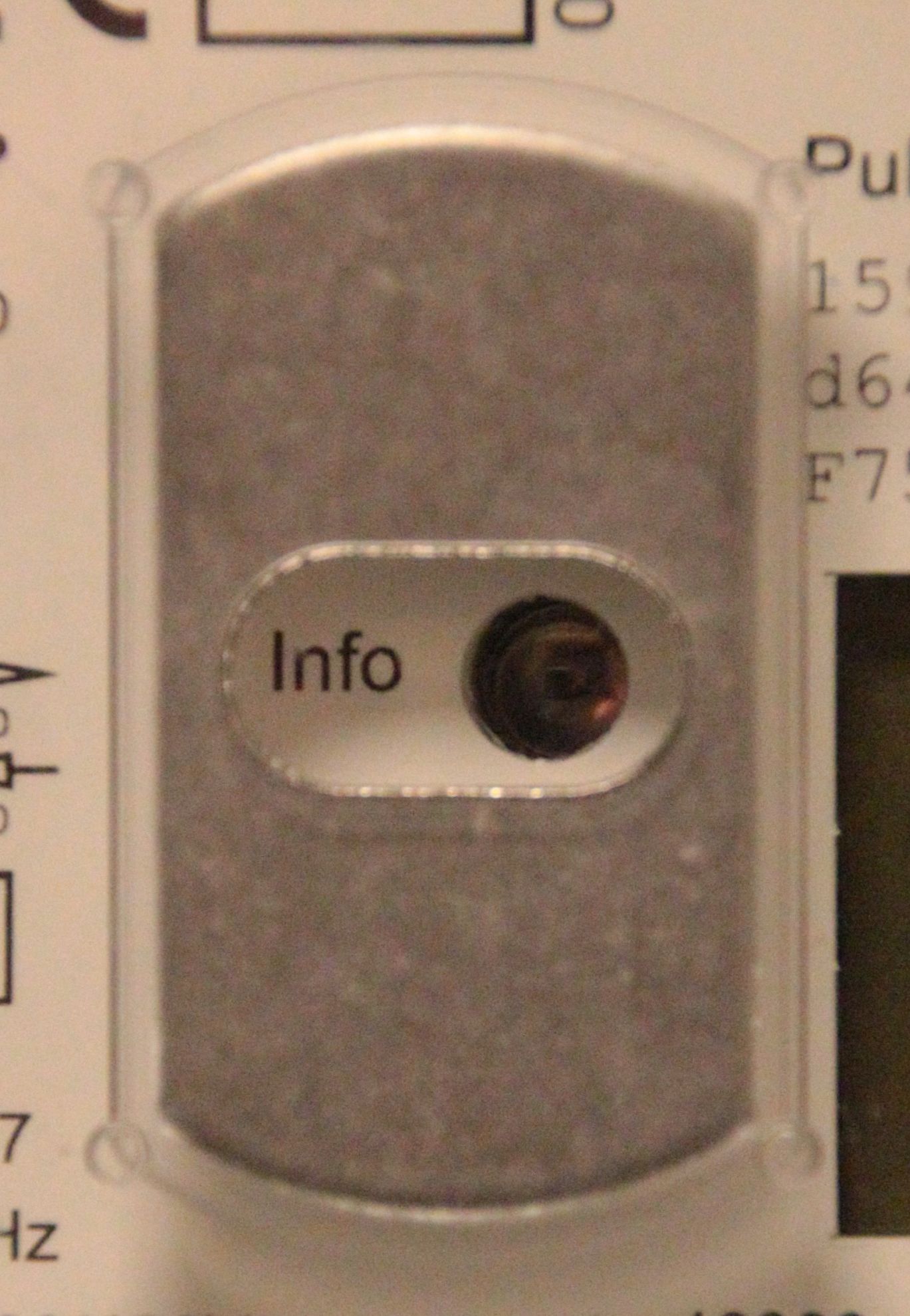
The installation of my fuel cell heating required a bi-directional power meter. Bonn Netz, my local power network provider, uses meters of type EasyMeter Q3M which have two infrared interfaces: A bidirectional D0 interface, and a read-only info interface. I use the info interface (INFO-DSS) to read out power consumption and production of the three phases. For this, I built an optical interface, a 3D printed housing for it, and use the UART of a Raspberry Pi with python to get the values.
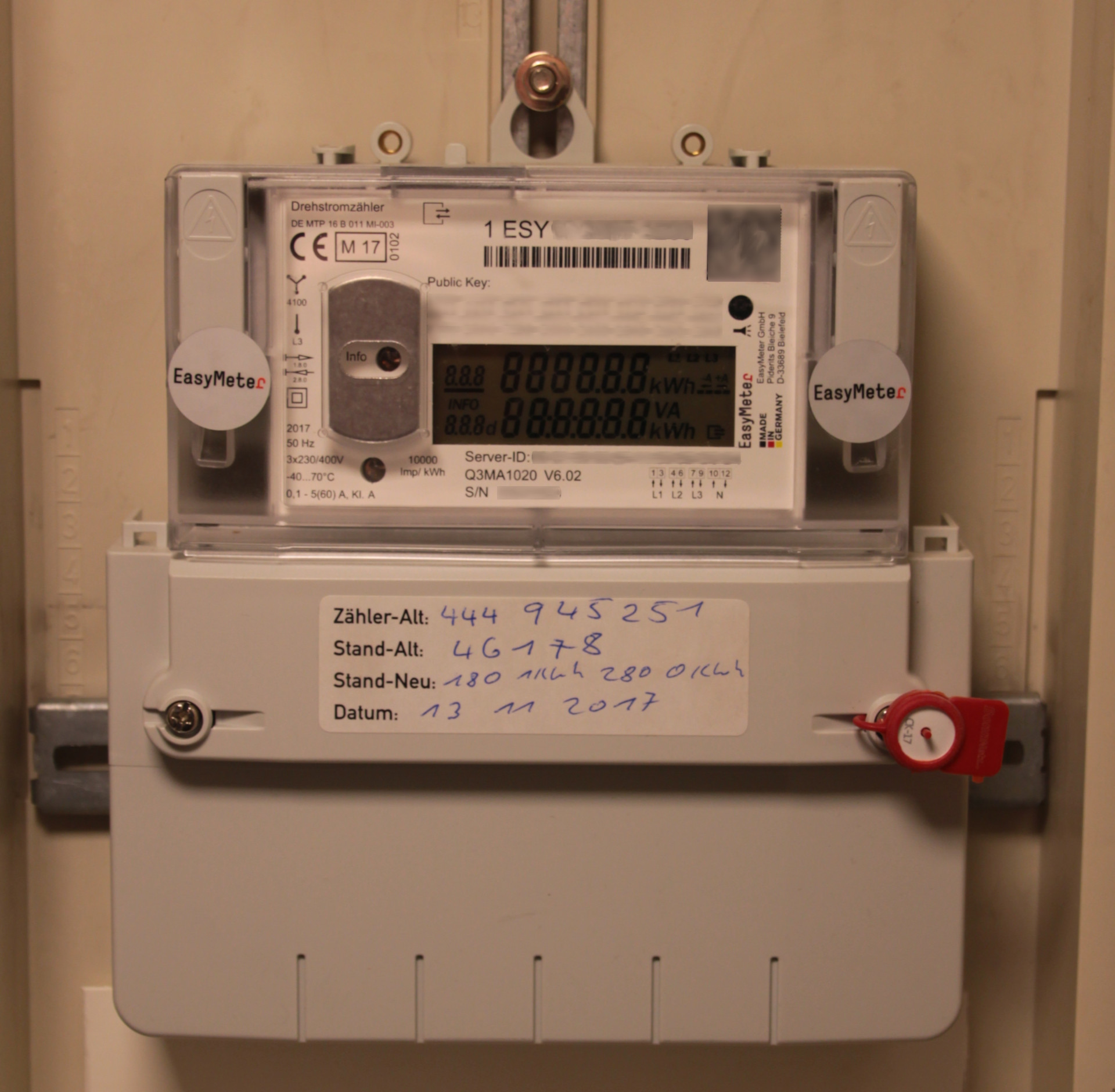
The Power Meter
The EasyMeter Q3M’s documentation (in German) states that the infrared interfaces run at 9600,8,N,1 and use the protocol “Smart Meter Language” SML 1.03, which seems to be a pure German “Standard”. The bi-directional interface is sealed, so I could not access it, but the info interface is freely accessible from the front of the device.
Unleashing the Full Power of the INFO-DSS Interface
When the power meter is delivered, it only outputs the summary energy consumption, but not the full set with the information on the individual phases. But the manual says that there is a PIN to unlock the full information set. I wrote an email to Bonn Netz and asked for the PIN, and they sent it out to me, professional in a sealed letter like an online banking PIN! Cool, thanks Bonn Netz! The PIN needs to be keyed in using a flashlight and moving it across a light sensor – a bit cumbersome, but a good idea to have a fully sealed housing and no mechanical parts. Worked very well in the end!
Electronics
I started with the interface that Sven Jordan describes on his webpage (German), but I could not get the exact same components. With those I got, the signals coming out from the circuit, even after changing the resistors, were awful and did not register with the UART. So I used half the circiut that makes up the OptoLink adapter for my Viessmann heating, which works nicely. Here’s how I did it:
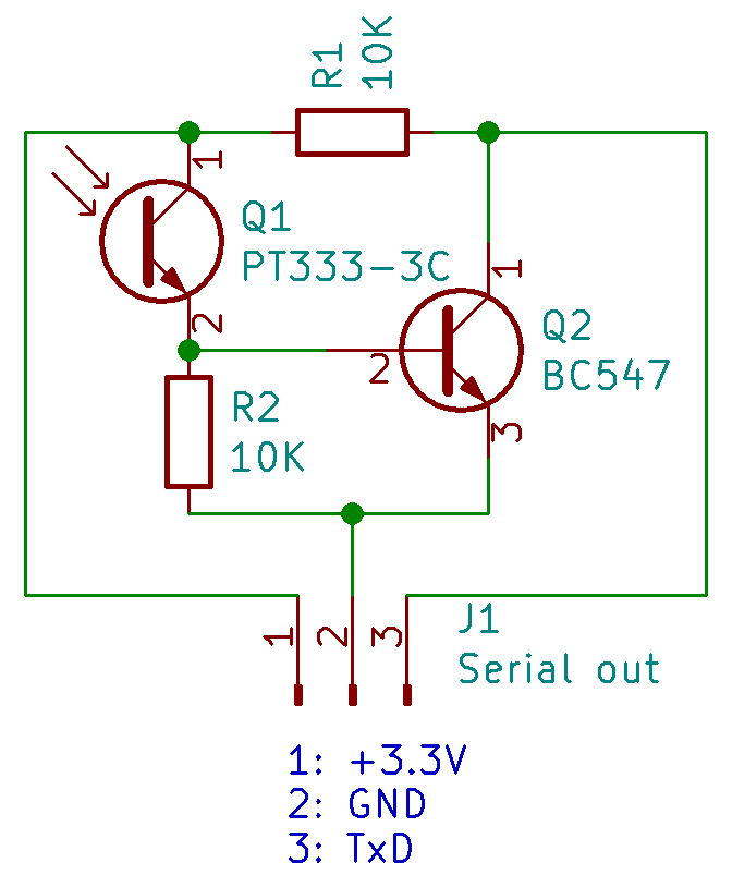
Parts add up to approximatly 1,- €. The IR phototransistor PT333-3C was the cheapest on stock at Conrad Bonn, so I took it – I guess more or less any IR phototransistor should work. From comparing a few datasheets, most are very similar in terms of specification, and the wavelength sensitivity covers such a broad window, that any should work.
And here’s how to connect it to the Raspberry Pi:
| Circuit pin | Function | Raspberry GPIO pin | Function |
| 1 | 3.3 V | 1 | 3.3 V |
| 2 | GND | 6 | GND |
| 3 | TxD | 10 | RxD |
Starting now to make my own PCBs using the CNC mill in my Fabtotum Personal Fabricator, I advanced a bit in KiCad. Here’s what came out:
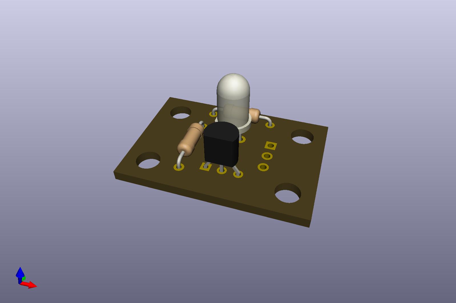
You can download the EasyMeter Interface KiCad files here.
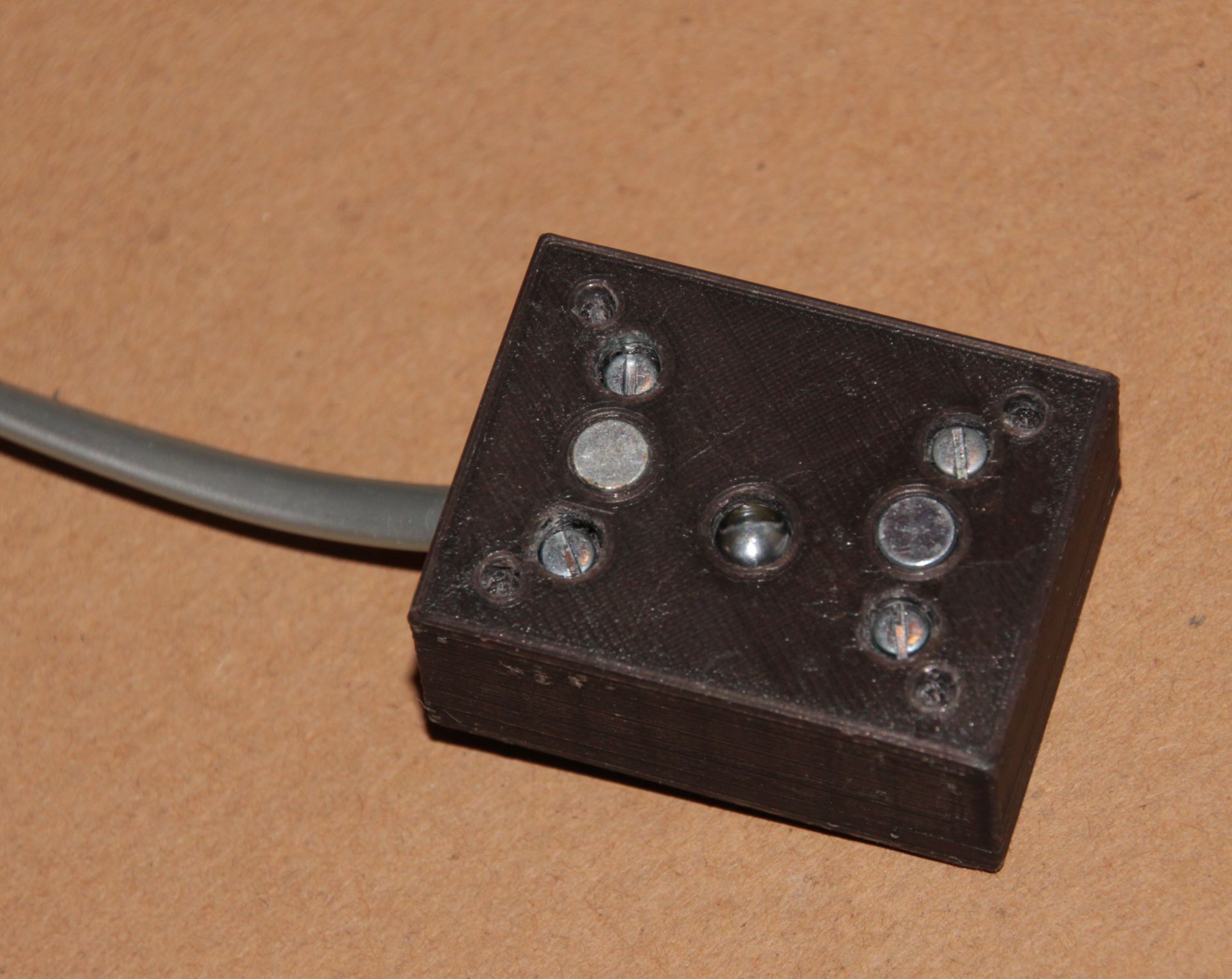
Housing
Now having my own 3D printer, the aforementioned Fabtotum, I created a housing for the circuit:

The housing has the following features:
- The KiCad designed PCB fits snugly into it, with the photo transistor matching up exactly with the IR emitter of the EasyMeter.
- The bottom side has holes to match the fixation notches of the EasyMeter.
- The bottom side has holes to put neodym magnets into which hold the box in place. However, the magnets I had (cylindrical with 5 mm diameter and 3 mm height) are barely strong enough, so perhaps you want to find stronger ones and modify the housing accordingly.
- It has an outlet for a flat 4 wire telephone cable that can be put either on top or bottom of the housing.
- Four 2 mm screws of 18 mm length with matching nuts hold everything together.
You may download the 3D model files for the housing here or from Thingiverse. I was a bit optimistic with regard to the notch and screw holes – I had to widen them with a drill. Perhaps you should modify them a bit before printing your own. By the way: I am totally surprised how well the 3D builder app that comes with Windows 10 works! It has a few nasty bugs, but all in all its surprisingly versatile and intuitive!
Software
As mentioned above, the meter “speaks” SML 1.03, which seems to be a German invention by the VDE. And personally I find it a rather crappy standard – I started to write a “generic” python implementation and gave up after half an hour, because a) the definition is over-complicated and b) the documentation is written in a *very* confusing way. So I followed the approach of Stefan Weigert (sorry, all in German) and just hard-coded the decodings. This is rather stupid and unflexible, but it does the job. Thanks to Stefan Weigert for publishing the code! The OBIS numbers used are explained in this document (you guessed it: in German…).
There is libSML, which is a generic implementation of SML written in C, and SMLlib for AVR, but I did not take the time to fiddle with these, since I am currently very python minded. There is also the Volkszähler project (surprise: German…) that’s worth a look if you want to do more.
So here is the code, based on Stefan Weigerts code from other smart meters:
|
1 2 3 4 5 6 7 8 9 10 11 12 13 14 15 16 17 18 19 20 21 22 23 24 25 26 27 28 29 30 31 32 33 34 35 36 37 38 39 40 41 42 43 44 45 46 47 48 49 50 51 52 53 54 55 56 57 58 59 60 61 62 63 64 65 66 67 68 69 70 71 72 73 74 75 76 77 78 79 80 81 82 83 84 85 86 87 88 89 90 91 92 93 94 95 96 97 98 99 100 101 102 103 104 105 106 107 108 109 110 111 112 113 114 115 116 117 118 119 120 121 122 123 124 125 126 127 128 129 130 131 132 133 134 135 136 137 138 139 140 141 142 143 144 145 146 147 148 149 150 151 152 153 154 155 156 157 158 159 160 161 162 163 164 165 166 167 168 169 170 171 172 173 174 175 176 177 178 179 180 181 182 183 184 185 186 187 188 189 190 191 192 193 194 195 196 197 198 199 200 201 202 203 204 205 206 207 208 209 210 211 212 213 214 215 216 217 218 |
#!/usr/bin/python # -*- coding: iso-8859-15 -*- # from: http://www.stefan-weigert.de/php_loader/sml.php # Modified for EasyMeter Q3M and translated to English by Hauke # http://projects.webvoss.de/2019/01/04/interfacing-easymeter-q3m-via-info-interface/ import time import serial from threading import Timer import sys mystring = "" crc16_x25_table = [ 0x0000, 0x1189, 0x2312, 0x329B, 0x4624, 0x57AD, 0x6536, 0x74BF, 0x8C48, 0x9DC1, 0xAF5A, 0xBED3, 0xCA6C, 0xDBE5, 0xE97E, 0xF8F7, 0x1081, 0x0108, 0x3393, 0x221A, 0x56A5, 0x472C, 0x75B7, 0x643E, 0x9CC9, 0x8D40, 0xBFDB, 0xAE52, 0xDAED, 0xCB64, 0xF9FF, 0xE876, 0x2102, 0x308B, 0x0210, 0x1399, 0x6726, 0x76AF, 0x4434, 0x55BD, 0xAD4A, 0xBCC3, 0x8E58, 0x9FD1, 0xEB6E, 0xFAE7, 0xC87C, 0xD9F5, 0x3183, 0x200A, 0x1291, 0x0318, 0x77A7, 0x662E, 0x54B5, 0x453C, 0xBDCB, 0xAC42, 0x9ED9, 0x8F50, 0xFBEF, 0xEA66, 0xD8FD, 0xC974, 0x4204, 0x538D, 0x6116, 0x709F, 0x0420, 0x15A9, 0x2732, 0x36BB, 0xCE4C, 0xDFC5, 0xED5E, 0xFCD7, 0x8868, 0x99E1, 0xAB7A, 0xBAF3, 0x5285, 0x430C, 0x7197, 0x601E, 0x14A1, 0x0528, 0x37B3, 0x263A, 0xDECD, 0xCF44, 0xFDDF, 0xEC56, 0x98E9, 0x8960, 0xBBFB, 0xAA72, 0x6306, 0x728F, 0x4014, 0x519D, 0x2522, 0x34AB, 0x0630, 0x17B9, 0xEF4E, 0xFEC7, 0xCC5C, 0xDDD5, 0xA96A, 0xB8E3, 0x8A78, 0x9BF1, 0x7387, 0x620E, 0x5095, 0x411C, 0x35A3, 0x242A, 0x16B1, 0x0738, 0xFFCF, 0xEE46, 0xDCDD, 0xCD54, 0xB9EB, 0xA862, 0x9AF9, 0x8B70, 0x8408, 0x9581, 0xA71A, 0xB693, 0xC22C, 0xD3A5, 0xE13E, 0xF0B7, 0x0840, 0x19C9, 0x2B52, 0x3ADB, 0x4E64, 0x5FED, 0x6D76, 0x7CFF, 0x9489, 0x8500, 0xB79B, 0xA612, 0xD2AD, 0xC324, 0xF1BF, 0xE036, 0x18C1, 0x0948, 0x3BD3, 0x2A5A, 0x5EE5, 0x4F6C, 0x7DF7, 0x6C7E, 0xA50A, 0xB483, 0x8618, 0x9791, 0xE32E, 0xF2A7, 0xC03C, 0xD1B5, 0x2942, 0x38CB, 0x0A50, 0x1BD9, 0x6F66, 0x7EEF, 0x4C74, 0x5DFD, 0xB58B, 0xA402, 0x9699, 0x8710, 0xF3AF, 0xE226, 0xD0BD, 0xC134, 0x39C3, 0x284A, 0x1AD1, 0x0B58, 0x7FE7, 0x6E6E, 0x5CF5, 0x4D7C, 0xC60C, 0xD785, 0xE51E, 0xF497, 0x8028, 0x91A1, 0xA33A, 0xB2B3, 0x4A44, 0x5BCD, 0x6956, 0x78DF, 0x0C60, 0x1DE9, 0x2F72, 0x3EFB, 0xD68D, 0xC704, 0xF59F, 0xE416, 0x90A9, 0x8120, 0xB3BB, 0xA232, 0x5AC5, 0x4B4C, 0x79D7, 0x685E, 0x1CE1, 0x0D68, 0x3FF3, 0x2E7A, 0xE70E, 0xF687, 0xC41C, 0xD595, 0xA12A, 0xB0A3, 0x8238, 0x93B1, 0x6B46, 0x7ACF, 0x4854, 0x59DD, 0x2D62, 0x3CEB, 0x0E70, 0x1FF9, 0xF78F, 0xE606, 0xD49D, 0xC514, 0xB1AB, 0xA022, 0x92B9, 0x8330, 0x7BC7, 0x6A4E, 0x58D5, 0x495C, 0x3DE3, 0x2C6A, 0x1EF1, 0x0F78] class Watchdog_timer: def __init__(self, timeout, userHandler=None): self.timeout = timeout self.handler = userHandler if userHandler is not None else self.defaultHandler self.timer = Timer(self.timeout, self.handler) self.timer.start() def reset(self): self.timer.cancel() self.timer = Timer(self.timeout, self.handler) self.timer.start() def stop(self): self.timer.cancel() def defaultHandler(self): raise self def crc16_x25(Buffer): crcsum = 0xffff global crc16_x25_table for byte in Buffer: crcsum = crc16_x25_table[(ord(byte) ^ crcsum) & 0xff] ^ (crcsum >> 8 & 0xff) crcsum ^= 0xffff return crcsum def signedintstr(hexstr): source = hexstr.encode('hex') sign_bit_mask = 1 << (len(source)*4-1) other_bits_mask = sign_bit_mask - 1 value = int(source, 16) return -(value & sign_bit_mask) | (value & other_bits_mask) def watchdogtimer_ovf(): global mystring sys.stdout.write("SML-Stream:\n" + mystring.encode('hex') + "\n\n") # output full telegram message = mystring[0:-2] # cut away the last bytes crc_rx = int((mystring[-1] + mystring[-2]).encode('hex'), 16) # exchange CRC bytes and tore them crc_calc = crc16_x25(message) # create own CRC for comparison if crc_rx == crc_calc: # compare CRCs - continue on match sys.stdout.write("crc OK\n") if message[0:8] == '\x1b\x1b\x1b\x1b\x01\x01\x01\x01': # check if first 8 bytes follow standard sys.stdout.write("SML start found\n\n") sys.stdout.write("____________________________________\n") sys.stdout.write("TransactionId: " + message[10:14] + message[14:20].encode('hex') + "\n") sys.stdout.write("GroupNo: " + message[21:22].encode('hex') + "\n") sys.stdout.write("abortOnError: " + message[23:24].encode('hex') + "\n") sys.stdout.write("getOpenResponse: " + message[31:34] + "\n") sys.stdout.write("reqFileId: " + message[35:38] + message[38:42].encode('hex') + "\n") sys.stdout.write("serverId: " + message[43:53].encode('hex') + "\n") sys.stdout.write("crc: " + message[56:58].encode('hex') + "\n") sys.stdout.write("____________________________________\n") sys.stdout.write("TransactionId: " + message[61:65] + message[65:71].encode('hex') + "\n") sys.stdout.write("GroupNo: " + message[72:73].encode('hex') + "\n") sys.stdout.write("abortOnError: " + message[74:75].encode('hex') + "\n") sys.stdout.write("getListResponse: " + message[77:79].encode('hex') + "\n") sys.stdout.write("serverId: " + message[82:92].encode('hex') + "\n") sys.stdout.write("listName: " + message[93:100].encode('hex') + "\n") sys.stdout.write("___\n") sys.stdout.write("choice(01=secIndex): " + message[102:103].encode('hex') + "\n") sys.stdout.write("secIndex(uptime): " + str(int(message[104:108].encode('hex'),16)) + "\n") sys.stdout.write("___\n") sys.stdout.write("objName: " + message[111:117].encode('hex') + " = OBIS-number for vendor ID\n") sys.stdout.write("Vendor ID: " + message[122:125] + "\n") sys.stdout.write("___\n") sys.stdout.write("objName: " + message[128:134].encode('hex') + " = OBIS-number for ServerID\n") sys.stdout.write("Server ID: " + message[139:149].encode('hex') + "\n") sys.stdout.write("___\n") sys.stdout.write("objName: " + message[152:158].encode('hex') + " = OBIS-number for cumulated incoming effective power (no rate assigned)\n") sys.stdout.write("???: " + message[159:162].encode('hex') + "\n") sys.stdout.write("unit: " + message[164:165].encode('hex') + " (Unit 1E=Wh)\n") sys.stdout.write("scaler: " + message[166:167].encode('hex') + " (Factor FC = -4 = 10^-4 = /10000) - /1000 to convert to kWh\n") sys.stdout.write("Incoming: " + str(int(message[168:176].encode('hex'),16)/10000000.0) + " kWh\n") sys.stdout.write("___\n") sys.stdout.write("objName: " + message[179:185].encode('hex') + " = OBIS-number for cumulated outgoing effective power (no rate assigned)\n") sys.stdout.write("???: " + message[186:189].encode('hex') + "\n") sys.stdout.write("unit: " + message[191:192].encode('hex') + " (Unit 1E=Wh)\n") sys.stdout.write("scaler: " + message[193:194].encode('hex') + " (Factor FC = -4 = 10^-4 = /10000) - /1000 to convert to kWh\n") sys.stdout.write("Outgoing: " + str(int(message[195:203].encode('hex'),16)/10000000.0) + " kWh\n") sys.stdout.write("___\n") sys.stdout.write("objName: " + message[206:212].encode('hex') + " = OBIS-number for cumulated incoming effective power rate 1\n") sys.stdout.write("unit: " + message[215:216].encode('hex') + " (Unit 1E=Wh)\n") sys.stdout.write("scaler: " + message[217:218].encode('hex') + " (Factor FC = -4 = 10^-4 = /10000) - /1000 to convert to kWh\n") sys.stdout.write("Incoming: " + str(int(message[219:227].encode('hex'),16)/10000000.0) + " kWh\n") sys.stdout.write("___\n") sys.stdout.write("objName: " + message[230:236].encode('hex') + " OBIS-number for cumulated outgoing effective power rate 1\n") sys.stdout.write("unit: " + message[239:240].encode('hex') + " (Unit 1E=Wh)\n") sys.stdout.write("scaler: " + message[241:242].encode('hex') + " (Factor FC = -4 = 10^-4 = /10000) - /1000 to convert to kWh\n") sys.stdout.write("Outgoing: " + str(int(message[243:251].encode('hex'),16)/10000000.0) + " kWh\n") sys.stdout.write("___\n") sys.stdout.write("objName: " + message[254:260].encode('hex') + " = OBIS-number for cumulated incoming effective power rate 2\n") sys.stdout.write("unit: " + message[263:264].encode('hex') + " (Unit 1E=Wh)\n") sys.stdout.write("scaler: " + message[265:266].encode('hex') + " (Factor FC = -4 = 10^-4 = /10000) - /1000 to convert to kWh\n") sys.stdout.write("Incoming: " + str(int(message[267:275].encode('hex'),16)/10000000.0) + " kWh\n") sys.stdout.write("___\n") sys.stdout.write("objName: " + message[278:284].encode('hex') + " OBIS-number for cumulated outgoing effective power rate 2\n") sys.stdout.write("unit: " + message[287:288].encode('hex') + " (Unit 1E=Wh)\n") sys.stdout.write("scaler: " + message[289:290].encode('hex') + " (Factor FC = -4 = 10^-4 = /10000) - /1000 to convert to kWh\n") sys.stdout.write("Outgoing: " + str(int(message[291:299].encode('hex'),16)/10000000.0) + " kWh\n") sys.stdout.write("___\n") sys.stdout.write("objName: " + message[302:308].encode('hex') + " OBIS-number current effective power total\n") sys.stdout.write("unit: " + message[311:312].encode('hex') + " (Unit 1B=W)\n") sys.stdout.write("scaler: " + message[313:314].encode('hex')+ " Factor FE = -2 = 10^-2 = /100\n") sys.stdout.write("Current effective power total: " + str(signedintstr(message[315:323])/100.0)+ " W\n") sys.stdout.write("___\n") sys.stdout.write("objName: " + message[326:332].encode('hex') + " OBIS-number current effective power L1\n") sys.stdout.write("unit: " + message[335:336].encode('hex') + " (Unit 1B=W)\n") sys.stdout.write("scaler: " + message[337:338].encode('hex')+ " Factor FE = -2 = 10^-2 = /100\n") sys.stdout.write("Current effective power L1: " + str(signedintstr(message[339:347])/100.0)+ " W\n") sys.stdout.write("___\n") sys.stdout.write("objName: " + message[350:356].encode('hex') + " OBIS-number current effective power L2\n") sys.stdout.write("unit: " + message[359:360].encode('hex') + " (Unit 1B=W)\n") sys.stdout.write("scaler: " + message[361:362].encode('hex')+ " Factor FE = -2 = 10^-2 = /100\n") sys.stdout.write("Current effective power L2: " + str(signedintstr(message[363:371])/100.0)+ " W\n") sys.stdout.write("___\n") sys.stdout.write("objName: " + message[374:380].encode('hex') + " OBIS-number current effective power L3\n") sys.stdout.write("unit: " + message[383:384].encode('hex') + " (Unit 1B=W)\n") sys.stdout.write("scaler: " + message[385:386].encode('hex')+ " Factor FE = -2 = 10^-2 = /100\n") sys.stdout.write("Current effective power L3: " + str(signedintstr(message[387:395])/100.0)+ " W\n") sys.stdout.write("___\n") sys.stdout.write("objName: " + message[398:404].encode('hex') + " OBIS-number for Public Key\n") sys.stdout.write("value: " + message[410:458].encode('hex') + " (Public Key)\n") sys.stdout.write("___\n") sys.stdout.write("crc: " + message[462:464].encode('hex') + "\n") sys.stdout.write("____________________________________\n") sys.stdout.write("TransactionId: " + message[467:471] + message[471:477].encode('hex') + "\n") sys.stdout.write("GroupNo: " + message[478:479].encode('hex') + "\n") sys.stdout.write("abortOnError: " + message[480:481].encode('hex') + "\n") sys.stdout.write("getCloseResponse: " + message[483:485].encode('hex') + "\n") sys.stdout.write("crc: " + message[488:490].encode('hex') + "\n") sys.stdout.write("\n") watchdog.stop() mystring="" else: sys.stdout.write("no SML\n\n") mystring="" watchdog.stop() else: sys.stdout.write("crc NOK\n\n") mystring="" watchdog.stop() try: my_tty = serial.Serial(port='/dev/ttyAMA0', baudrate = 9600, parity =serial.PARITY_NONE, stopbits=serial.STOPBITS_ONE, bytesize=serial.EIGHTBITS, timeout=0) sys.stdout.write(my_tty.portstr + " opened\n\n") my_tty.close() my_tty.open() except Exception, e: sys.stdout.write("serial port could not be opened:\n" + str(e) + "\n\n") exit() try: my_tty.reset_input_buffer() my_tty.reset_output_buffer() watchdog = Watchdog_timer(0.1, watchdogtimer_ovf) watchdog.stop() while True: while my_tty.in_waiting > 0: mystring += my_tty.read() watchdog.reset() except KeyboardInterrupt: my_tty.close() sys.stdout.write("\nProgram stopped manually!\n") |
In order for that to work you may need to modify the Raspberry Pi serial configuration as desribed in my OptoLink blog post.
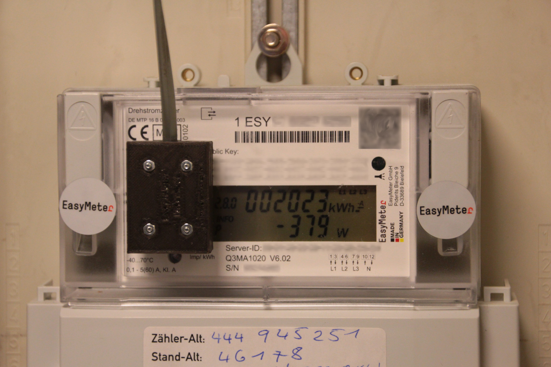
Here’s a picture of the interface in place:
Final Remarks
My thanks go to Sven Jordan, Stefan Weigert, the authors of KiCad, Microsoft (sic!) for 3D builder, and to Bonn Netz!
i do not have a pin… perhaps you can mail me yours for testing? thank you veray much!
Hi Stephan,
my PIN would not work for your meter, they are assigned individually. I just PM’d you and sent you the details about how I got my PIN from Bonn Netz.
Good luck!
Hauke
Note to myself: Just stumbled accross this page (surprise: in German…) – It seems that even my oldfashioned mechanic gas meter can be accessed “electronically” – new project born 🙂
Hi Hauke,
would be great if you could drop me a private mail on how you made your provider to hand out that pin.
Thank’s in advance.
Stephan
Will do 🙂 But it’s basically as I wrote in the post: I e-mailed my provider, and received the PIN letter without much ado.
Hi Hauke,
wie sind denn Deine Erfahrungen im Dauerbetrieb? Ist die Infoschnittstelle (vorne am Gehäuse) wirklich sinnvoll und auf Dauer nutzbar? Warum ich frage: Im Wiki von volkszähler.org (https://wiki.volkszaehler.org/hardware/channels/meters/power/edl-ehz/easymeter_q3m) steht:
“Die Infoschnittstelle liefert die Detailwerte NUR solange das Display mit PIN aktiv ist. Danach werden wieder nur die alten Werte geliefert. Besser also die MSB Schnittstelle nehmen, da funktioniert es dauerhaft nach PIN Eingabe und freischalten der Info-Funktion.”
Die MSB-Schnittstelle ist ja oben am Gehäuse und mit einem Klebeband versehen, das entfernt werden muss.
Hi Herbert,
bei mir ist die Info-Schnittstelle seit ich die PIN eingegeben habe dauerhaft “offen”. Ich muss zwar einschränken, dass ich aktuell den Lesekopf nicht in Betrieb habe und mich evtl. irre, aber mit Eingabe der PIN hat sich auch die Basisanzeige des Zählers verändert, und das ist bis heute so.
Die MSB-Schnittstelle ist bei mir auch zugeklebt, und ich zögere, das einfach zu entfernen. Ich bin mir unsicher, ob ich das einfach so darf.
Viele Grüße
Hauke
Hallo Herbert!
Ich habe heute erfolgreich mein Easymeter angezapft. Danke Hauke für diese Anleitung.
Derzeit habe ich auch noch keinen “Code” für die ausführlichen Infos, habe aber eine Email an meinen Versorger geschickt.
Sobald du den Code “eingeleuchtet” hast, gibt es zwei weitere Menüpunkte. Dort kannst du erstens die Codeabfrage abschalten und zweitens die erweiterten Infos auf “dauerhaft” einstellen. Das hat mir ein Kollege bestätigt und ich habe es auch in der Anleitung zum Easymeter gelesen.
Viele Grüße
denkste! Was bei meinem Kollegen funktioniert, ist bei mir nicht vorhanden.
Leider waren bei mir die Menüpunkte zum dauerhften Abschalten der PIN oder zum dauerhaften Einschalten der erweiterten Infos ab Werk auskonfiguriert. Ich mußte dann den Fototransistor auch notgedrungen über die MSB-Schnittstelle ankoppeln, die sich auf der Oberseite befindet. Meinen vollständigen Bericht zur Realisierung gibt es hier:
https://www.hgct.de/stromzaehler-easymeter-q3ma1020-auslesen
Viele Grüße
Jens
Hallo Hauke,
danke für den Beitrag. Er war eine Inspiration für mich. Ich habe auch so einen EasyMeter Q3M im Schaltkasten. Nachdem die bidirektionale Schnittstelle versiegelt ist, habe ich mich nicht weiter damit auseinandergesetzt. Aufgrund dieses Beitrags habe ich mich mit einer Taschenlampe bewaffnet und … der Zähler versteht mich. Dann habe ich meinen Netzbetreiber nach der PIN gefragt und … nach ein paar Tagen habe ich sie bekommen. Nach der Eingabe der Pin bleibt bei mir die zusätzliche Anzeige aktuell dauerhaft bestehen.
Parallel habe ich mir die Bauteile besorgt und die Schaltung auf einem Steckbrett aufgebaut und … mit einer IR-Quelle funktioniert sie. Nächster Schritt ist die Schaltung an die Info-LED des Zählers zu bekommen und einen Raspi mit dem Programm zu beladen. Glücklicher Weise liegt noch ein Raspi in der Bastelkiste. Aktuell sind sie schwer zu bekommen.
Hierzu eine Frage: Beim Versuch das Programm welches hier abgedruckt ist zu verstehen habe ich ein paar Fragezeichen:
1) An welchem Pin erwartet der Raspi das Signal von der Info-LED?
2) Was macht das Programm dann mit den Signal? Es wird encodiert und … kommt es zu einer Ausgabe der Werte die im Datenstrom liegen im Klartext auf der console?
Gruß
Eckart
Hallo Eckart,
bzgl. des Eingangspins ist die Zeile 196 im Code relevant:
my_tty = serial.Serial(port='/dev/ttyAMA0', baudrate = 9600, parity =serial.PARITY_NONE, stopbits=serial.STOPBITS_ONE, bytesize=serial.EIGHTBITS, timeout=0)Hier wird die serielle Schnittstelle ausgewählt, die verwendet werden soll. Bei älteren Raspberries gab es nur eine, der aktuelle Raspberry hat glaube ich 5. Wenn Du wie im Code beschrieben /dev/ttyAMA0 verwendest, dann musst Du den TxD-Ausgang der Info-DSS-Schaltung an Pin 10 des Raspberry (RxD) anschließen. Das ist der Standard-Serielle-Port.
Das Programm entschlüsselt den Input der Info-DSS-Diode und stellt ihn lesbar auf dem Bildschirm dar. Das Programm ist in Python geschrieben, d.h. Du musst es in eine Datei auf dem Raspberry speichern (z.B. zaehler.py) und diese dann mit dem Kommando
python zaehler.pyaufrufen. Das Programm wartet dann auf Input von der seriellen Schnittstelle, versucht den zu dekodieren und stellt es lesbar dar. Und zwar so lange, wie Du willst – ggf. mit Ctrl+C abbrechen.
Es ist evtl. möglich, dass python sich darüber beschwert, dass ihm Module fehlen – die muss man dann ggf. noch nachinstallieren. Falls Du da an Grenzen stößt, schreibe mich gerne an, dann helfe ich.
Viel Erfolg!
Hauke
Danke für die Aufhellung. Ich bin jetzt eine Stufe weiter aber noch nicht beim Raspi. Ich habe die Schaltung nun auf einer Platine in einer Form die an den Zähler passt. Bevor ich nun mit dem Raspi auswerte, möchte ich sicher sein, dass es am Zähler funktioniert. (“Weniger Unbekannte”). Mit der Handykamera sehe ich, dass die Info-LED mit ca. 1 Hz blinkt. Aber aus meiner Schaltung kommt aber nix raus. Wenn ich den IR-Transistor mit einer Fernbedienung “beleuchte” sehe ich das die Schaltung funktioniert. Hast du eine Idee, warum meine Info-LED keine Reaktion auslöst?
Der Fehler lag in meinem Schaltungsaufbau. Die Schaltung war scheinbar komplex genug um einen Fehler einzubauen. Der Fehler führte dazu, dass es teilweise funktionierte. Was mich zur Vermutung brachte, dass speziell die Info-LED nicht erkannt wird. Das war aber nicht der Fall. Wenn man deine Schaltung richtig aufbaut, funktioniert es auch an meiner Info-LED.
Jetzt komme ich zum nächsten Schritt, Raspi in Betrieb nehmen und anschliessen…
Gut zu hören – ich hatte noch keine Zeit, über Deine letzte Anfrage nachzudenken, von daher: Um so besser dass es nun geht 🙂
Gut, nun habe ich einen Raspi 2 mit aktuellem Betriebssystem versorgt und habe das Script von deiner Seite in meinen Heimatordner auf dem Pi kopiert. Ich gehe davon aus, dass es ein Python3 Script ist? Also starte ich es mit “python3 zaehler_auslesen.py”. Wenn ich dies tue, kommt diese Fehlermeldung:
File “/home/pi/zaehler_auslesen.py”, line 201
except Exception, e:
Kannst du mir sagen, was ich hier falsch gemacht habe? Grundsätzlich scheint er den Code ja bis Zeile 201 schon mal zu mögen…
Ist glaube ich noch für Python 2 geschrieben, ich habe erst recht spät auf Python 3 umgestellt.. Probier’s mal mit “python zaehler_auslesen.py”.
Den beschriebenen Fehler habe ich bei diesen Aufrufen:
“python3 zaehler_auslesen.py”
“python zaehler_auslesen.py”
beim diesem Aufruf:
“python2 zaehler_auslesen.py”
kommt diese Fehlermeldung:
Traceback (most recent call last):
File “zaehler_auslesen.py”, line 9, in
import serial
ImportError: No module named serial
Ich habe den Eindruck, wenn ich “python” verwende startet er “python3”. Nur wenn ich explizit “python2” verwende startet er “python2”. Ist das vielleicht eine Voreinstellung per Installation?
– Unterscheiden sich python2 und python3 relevant bezogen auf dein Programm?
– muss das Programm in einem bestimmten Ordner liegen? Bei mir liegt es im Home…
mein Verdacht bestätigt sich:
python2 –version ergibt 2.7.18
python3 –version ergibt 3.9.2
python –version ergibt 3.9.2
dein Programm ist definitiv ein python2 programm. Wenn ich es aber – wie oben beschrieben – mit python2 starte findet er schon das Modul “serial” nicht. Ist dieses Modul für python2 und python3 unteschiedlich? Sorry, wenn ich dich mich diesem Kinderkram nerve. Soll ich auf Englisch weiter schreiben, damit mehr Leser war davon haben?
Englisch/Deutsch: Wie Du magst – da die Diskussion nun schon in Deutsch läuft, bleiben wir vielleicht dabei.
OK, mit Freude sehe ich, dass python3 inzwischen der Standard ist im Raspberry OS – das war überfällig.
Zur Fehlermeldung in python2: es fehlt das serial-Modul für python 2. Du musst folgendes machen:
sudo apt install python-serialAlternativ musst Du das Programm nach Python 3 portieren, das ist vermutlich gar nicht so schwer, aber mit etwas Forschungsaufwand verbunden, wenn Du das noch nie gemacht hast. Evtl.ist es aber auch ganz einfach – ändere Zeile 201 nach
except Exception as e:Kannst ja mal gucken, ob es dann in Python 3 läuft.
Hi Hauke,
ok, danke für die weiteren Anregungen. Den Versuch mit
> except Exception as e:
hatte ich schon probiert. Leider fällt das Programm dann auf die Bretter wenn es zu einer Variablenumwandlung kommt. str-Variablen sind scheinbar auch eine “der” Unterschiede zwischen python2 + python3.
Also habe ich es doch mit dem Ansatz probiert auf mein aktuelles Pi OS python2 und dieses modul serial zu bekommen. Alle Versuche ohne Erfolg. Er findet das Modul nicht.
Dein Ansatz mit
> sudo apt install python-serial
führt leider auch nur zu einer Fehlermeldung:
“Package python-serial is not available, but is referred to by another package.
This may mean that the package is missing, has been obsoleted, or
is only available from another source”
Ich glaube ich brauche jetzt etwas Ablenkung… Vielleicht versuche ich es mal mit “p2to3.py”. Vielleicht komme ich so zu einem Skript in python3 syntax…
Jetzt war ich neugierig… Das Problem scheint nicht das str() zu sein, sondern das hex-Encoding – siehe hier auf Stackoverflow. Im Stackoverflow-Artikel sind auch Alternativen benannt.
In der aktuellen Bullseye-Disto scheint das phython2-serial-Paket anders zu heißen. Im Zweifelsfall statdessen so installieren:
pip2 install pyserialIch bevorzuge apt/Debian packages, aber wenn es nicht anders geht, dann eben pip…
Meine Versuche mit “pip2 install pyserial” und auch mit “2to3.py” waren auch nicht von Erfolg gekrönt. Darum habe ich einen radikalen Schritt gemacht und bin von dem python2 programm weg. Ich habe mich ein paar Abstraktionsschichten noch oben bewegt und ioBroker auf dem Raspi installiert. Dort gibt es fertige Module für meinen Stromzähler mit Info-LED. Und … flups ich kann meinen Zähler auslesen.
Mein Setup ist jetzt dein Lesekopf an einem Raspberry 2 und ioBroker. Nun folgen SQL-Datenbank, speichern der Werte und dann die Visualisierung. Danke für die Unterstützung!
Gruß Eckart