Interfacing Vitovalor 300-P with a Raspberry Pi
I want to integrate my new Viessmann Vitovalor 300-P fuel cell heating into my home automation. For this, I use the Optolink interface, vcontrold from the openv community, and create my own configuration files from several sources.
If you want to skip the introduction bla-bla, you may directly go to
- Building the OptoLink connector
- Setting up vcontrold on a Raspberry Pi
- The Vitovalor-specific XML configuration files
Disclaimer: Interfacing with your heating system as described here is happening at your own risk! There is no official support for this by Viessmann, and the methods shown here may potentially damage your device!
My New Fuel Cell Heating
Since a few weeks its in my cellar: A brand new heating that sports a fuel cell module! Top notch! 🙂 Its a Vitovalor 300-P by Viessmann. And of course I want to integrate this into my home automation! The heating comes with a LAN interface which connects it to Viessmann’s cloud service. This already allows me to use a smartphone to control the heating from abroad, and also offers a very detailed glance into every system parameter and measurement from the vitodata-website (very cool!), but there is no API to use for my own interfacing and purposes.
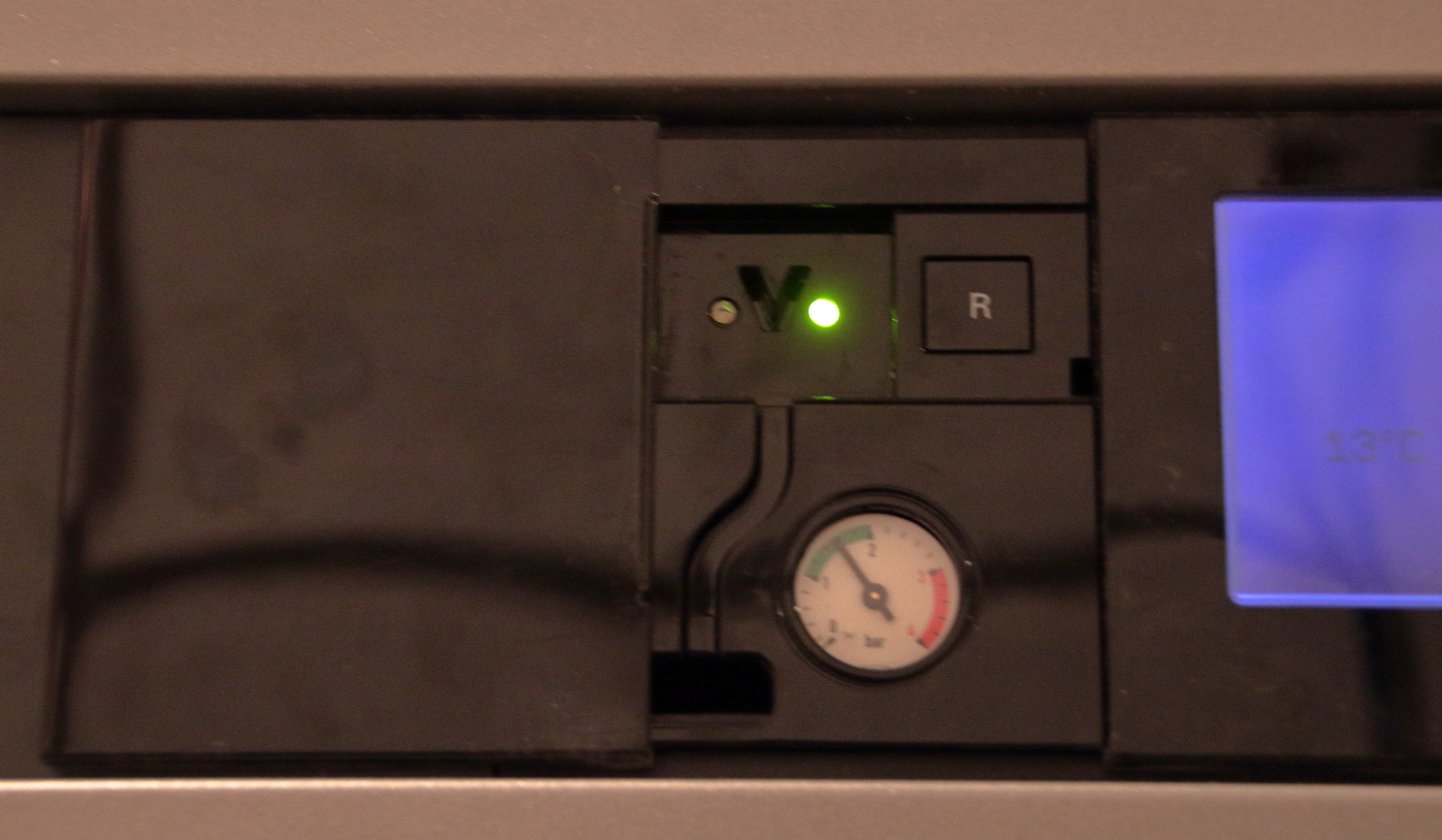
However, the heating features an OptoLink interface, which is basically an infrared (860 nm receiver, 880 nm sender) serial interface with a standard UART, using 4800 baud, 8bits, even parity and two stop bits with no handshake (4800,8,E,2). And since this is kind of a standard interface for nearly any Viessman heating since at least a decade, other enthusiasts have already done all the hard work to figure out how to interface with such heatings – mainly the openv project (mostly in German – sorry). Many, many thanks for their efforts and the great wiki pages and software!
There exists a simple and cheap circuit for interfacing with Raspberry Pi’s UART, and the vcontrold daemon that does all the communication with the heating, providing a concise command line interface via telnet for access from other programs. Really good work!
So, what remains to be done? Well, while OptoLink is kind of established, each and every Viessmann heating speaks its own dialect. vcontrold accepts an XML file that defines all commands the individual heating model understands; and here’s my todo: I need to work out the specifics of Vitovalor 300-P with its Vitotronic 200 RF HO1E control unit. Many commands are identical across a lot of heatings, but others are behaving differently for each model or exist just for one or a few models.
But first:
Building the OptoLink Connector
You can of course buy an original Viessmann Optolink cable, which does include an UART to USB bridge, but that sets you back by about 60 € – and where’s the fun? So I decided to build one myself, following the instructions for the Raspberry Pi UART interface from openv.
There is mainly one challange when building your own interface: The “V”. The V-shaped gap between sender and receiver is the only mechanical reference, and the original cable has a matching V-shaped protrusion to fit into the gap (Click here for an image of the original cable and the V shaped protrusion). Of course the best way would to 3D-print your own (and people have), but since I lack a 3D printer, I had to get creative.

First, I was lucky to find a plastic housing that nearly perfectly fit into the rectangular hole in front of the interface: A box that contained spring bars for wrist watches. It measures about 24 × 36 × 6 mm, which is slightly too broad, so you’ve to cut away the left and right flank. Perhaps you can find one at your local watchmakers or jewelers shop if you face the same task.

The transparant housing allowed to use a permanent marker to copy the V shape onto the plastic. Along these lines, I applied hot glue (several layers – 3D printing for the poor 🙂 ), which then, using a sharp paper knife, I cut into the required V shape. Worked nicely on first try! The plastic gets rather scratched, but who cares…
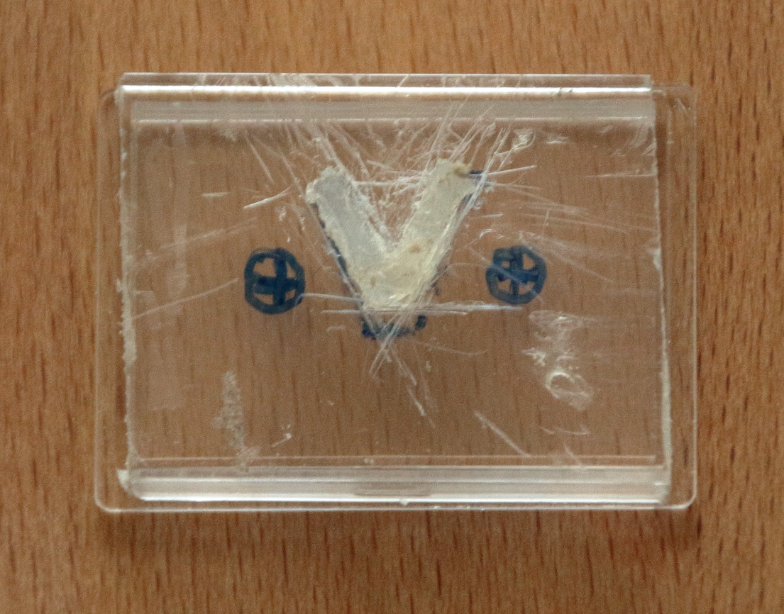
Next, the openv article warns you that, if not properly shielded, there may be cross-talk between sender and receiver. So I added heat shrink tube to the holes for the receiver and sender, fixating it with superglue (The image only shows one hole covered, but the second also received shrink tube. In the image you can also see the cut away flanks of the box that otherwise would make it too broad to fit).

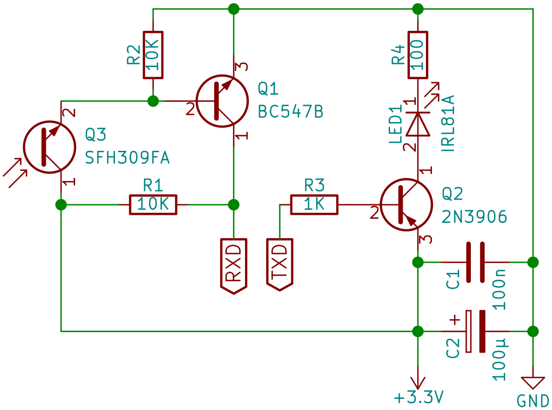
Openv strongly suggests a specific type of photo transistor and IR emitter diode, since others had problems with stray light or insufficient light transmission. While I was able to get the exact photo transistor, the IR LED is out of production. I searched for an IR LED with similar optical characteristics, and found IRL 81 A, wich as a side effect is much easier to fit into the confined space due to its form factor (click here for an image). Please be aware of the comment below by Eddy – it seems that my choices for IR sender/receiver are not best for all Viessmann Optolink interfaces. Although mine works just fine, I’d recommend to go for the elements Eddy suggests.
This LED requires a slightly different resistor. Also, because I had some issues due to the very long cable (about 10 m) I attached, I reduced the base resistor at the LED driver. So, here’s the part list and approximate cost:
Parts list
| 2 | 10 kΩ resistor | 0.01 € | |
| 1 | 1 kΩ resistor | 0.01 € | Instead of one 10 kΩ resistor in the original design |
| 1 | 100 Ω resistor | 0.01 € | Instead of 180 Ω resistor in original design |
| 1 | BC547B transistor | 0.20 € | |
| 1 | 2N3906 transistor | 0.05 € | |
| 1 | IRL 81 A infrared LED | 0.60 € | As replacement for the original SFH487-2 (But see comment below by Eddy) |
| 1 | SFH 309 FA infrared photo transistor | 0.25 € | (But see comment below by Eddy) |
| 1 | 100 nF capacitor | 0.05 € | |
| 1 | 100 μF electrolytic capacitor | 0.20 € | I first tried without this, but voltage drop was too strong with the long cable. I recommend to include this cap. |
| hole matrix board, hot glue, 4 wire telephone cable | 2.- € | Price estimated, had this lying around. The cable does not need to be shielded – 4800 baud, that’s about 10 kHz signal – easy for nearly any cable. | |
| # | Part | Price each (ca.) | Remarks |
About 3.50 € as compared to 60.- € for the genuine article – a bargain 🙂
The circuit
Assembling it All
There is not much space for all the parts to go into. Other makers have just used larger housings, but the Vitovalor has a sliding door in front of the Optolink, and since I later want to close it in the end (hiding my ugly result…), I lacked that freedom. So I cut a small strip of hole matrix board that fits exactly into the long side of the box:

Putting two wires into one hole and in three cases using “free flying soldering”, I was able to cram everything onto this:

Not the tidiest bit of circuit, but works! However, in retrospect I might have fared better cutting a second strip, putting one on the top of the box, the other at the bottom. Might have made the alignment of the optical parts easier. If you have the possibility to etch a PCB, I’d recommend to go for this SMD version – is much nicer!
Finally, I cut a hole into the box for the cable, attached it to the circuit, crammed everything into the box and closed the box with tape at the edges. Then I attached the whole thing into the Optolink at the heating:
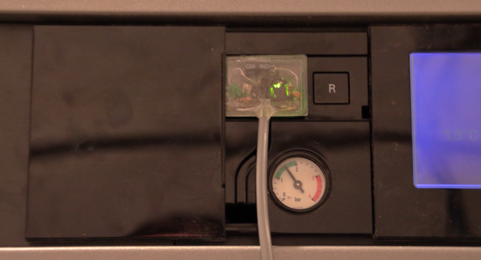
Works like a charm!
At the Raspberry, the pin assignments are:
| Circuit | Raspberry Pi Pin |
| 3.3 V | 1 |
| GND | 6 |
| TXD | 8 |
| RXD | 10 |
Setting up vcontrold on the Raspberry Pi
I was tempted to just refer to the openv wiki page, but since it is in German, I give the translated instructions here – as tested by me with Raspbian Stretch.
Prerequisites
You’ll need a few packages:
|
1 |
sudo apt-get install subversion automake autoconf telnet libxml2-dev |
Set up Serial Port
Since Raspberry Pi 3 the serial port assignments changed a bit. The “real” UART is assigned/reserved for Bluetooth. However, we need it for the interface. Also, we do not want the linux console to clutter the interface.
/boot/config.txt should contain these two lines:
|
1 2 |
enable_uart=1 dtoverlay=pi3-miniuart-bt |
and /boot/cmdline.txt should not contain console=serial0,115200 (or something similar). A reboot is required for this taking effect.
A more complete explanation can be found on this Raspberry foundation page.
Getting the Source Code, Compiling, Installation
This just takes a few minutes – no need to cross compile on a more powerful PC.
|
1 2 3 4 5 6 7 8 9 10 |
cd ~ mkdir openv cd openv svn checkout svn://svn.code.sf.net/p/vcontrold/code/trunk vcontrold-code cd vcontrold-code/vcontrold chmod +x auto-build.sh ./auto-build.sh ./configure make sudo make install |
After that, in /usr/local/bin there should be vcontrold, vclient and vsim.
Create and Edit /etc/vcontrold.xml
First, create a config directory and copy the template config files from the source into it:
|
1 2 3 |
sudo mkdir /etc/vcontrold sudo cp ~/openv/vcontrold-code/xml-32/xml/vito.xml /etc/vcontrold/ sudo cp ~/openv/vcontrold-code/xml-32/xml/vcontrold.xml /etc/vcontrold/ |
Modify the unix section of /etc/vcontrold.xml:
In section tty, change the interface to the Raspberry UART /dev/ttyAMA0.
In section net, add the IP ranges or addresses you’d like to access the data from.
Insert the device ID for your heating – the Vitovalor is 20E3. Other IDs you may find here. If your ID is not in the list and in case your heating also comes with access to the vitodata-server, go there to the heating, choose “Diagnostics”, open the device group and look for the ZE-ID. This is E3 for the Vitovalor, which means 20E3 as vcontrold ID.
|
1 2 3 4 5 6 7 8 9 10 11 12 13 14 15 16 17 18 |
<unix> <config> <serial> <tty>/dev/ttyAMA0</tty> </serial> <net> <port>3002</port> <allow ip='127.0.0.1'/> <allow ip='192.168.0.0/24'/> </net> <logging> <file>/tmp/vcontrold.log</file> <syslog>y</syslog> <debug>y</debug> </logging> <device ID="20E3"/> </config> </unix> |
Test
Try if the daemon comes up properly using vcontrold -n. This should open a telnet server on port 3002. Otherwise look into /tmp/vcontrold.log – this is often helpful for troubleshooting, also later when trying to figure out the commands.
Init-Script for vcontrold Autostart on Boot
Copy this script below to /etc/init.d/vcontrol – this is just copied from the opnev wiki page – all credits go there, or to be more precise to Michael Pucher (thanks a lot!). Then register the script:
|
1 2 3 |
cd /etc/init.d/ sudo chmod u+x vcontrol sudo update-rc.d vcontrol start 99 2 3 4 5 . stop 99 0 1 6 . |
And that’s it.
Using vcontrold
To access the heating via vcontrold, connect via telnet:
telnet localhost 3002
You’ll see a prompt. help will show you all available commands – in German… But the most interesting is the command commands – it shows all commands that you can send to the heating. Be aware that this is all at your own risk! As far as I understand, most of all is reverse engineered, and thus prone to errors that – worst case – might damage your heating! There is no official Viessmann support for the openv/vcontrold project.
Creating the Vitovalor-specific XML for vcontrold
The protocols implemented by the Viessmann heatings use address-value pairs. Some are read-only, others allow read/write operations. The vito.xml file contains the necessary definitions of addresses, values and units, along with the commands to get or set the values. The units vito.xml refers to are then defined in vcontrold.xml. While many addresses are the same across many Viessmann models, some are model-specific, or – worst case – have different meanings with different models.
Data Sources
It is not that easy to come by the addresses for a specific model. The following sources I used:
- The vito.xml files available in the openv pages (currently the old links, migration in progress):
Universal vito.xml[Edit Sept. 29th 2018 – link no longer valid, and could not find it in the new wiki anymore…]- two more
- the vito.xml included in the vcontrold source
- Coding lists from the manual and vitodata
- The datapoint lists for Vitogate 200 KNX – you must try to find someone at Viessmann who is willing to provide them. The page refers you to your local Viessmann sales agency, and indeed I got my list from them. Even if you do not use the Vitogate, the datapoint lists contain the right addresses.
- Educated guesses (there are some repeating patterns in the addresses which allow you to guess others) and trial-and-error
Totally not helpful was the Viessmann Community – the general idea is nice, but the people there are really reluctant to offer anything beyond simple information.
Addition in 2023: Reader Phil pointed me to the work of Sarnau, who harvested the official Vitosoft software from Viessmann for datapoints. Phil derived and published data point lists for OpenV from Sarnau’s work. Thanks for this great work! I yet have not included this information in my data below, not sure when I’ll find the time.
Educated Guessing of Addresses
There are some repeating patterns in the addresses with regard to the heat circuits/mixers. Often the first byte is indicating the heat circuit, the second the actual function. As an example:
0x2323 allows you to get/set the operation mode for heat circuit 1.
0x3323 does the same for heat circuit 2, and
0x4323 for heat circuit 3.
So, whenever you stumble across a working address 0x23??, it is worth to also try 0x33?? and 0x43??.
Here’s my list of “first bytes” I worked out for the three heat circuits:
| Heat circuit | First bytes |
| A1M1 or M1 | 0x20, 0x23, 0x25, 0x27, 0x29 |
| M2 | 0x30, 0x33, 0x35, 0x37, 0x39 |
| M3 | 0x40, 0x43, 0x45, 0x47, 0x49 |
Then, there are sometimes patterns in the second byte for heat circuits, and it seems to me that they are identical within the range of a first bye. An example:
0x0896, 0x0898 and 0x089A get the room temperatures for heat circuit 1, 2 and 3. And:
0x080A, 0x080C and 0x080E get the flow line temperatures for heat circuit 1, 2 and 3.
So I assumed (successfully) that within 0x08 any heat-circuit specific second byte may be used for the next heat circuit by adding an offset of 2 to it.
Here are the offsets I figured out (to be taken with a grain of salt – the statistics behind these assumptions are weak):
| First byte | Offset |
| 0x08 | 2 |
| 0x76 | 2 |
| 0xA4 | 64 (Hex: 40) |
Addresses Derived from Coding Lists
Both in the operation manual and in the vitodata server there are listings of the “Codings”. These give a single byte value in hex, so the aussmption is that these are part of an address. Matching a few addresses from existing vito.xml and the manual seem to confirm this. It looks like
- Codings that are not connected to a heat circuit go by address 0x77XX, where XX is the coding byte
- Codings that are assigned to heat circuits go by the addresses 0x27XX, 0x37XX and 0x47XX for heat circuit 1, 2 and 3, where again XX is the coding byte
I am currently testing this assumption, will update here as soon as I’m clear about it.
Short message inbetween (Nov. 28th): 0x27/37/47xx work all, 0x77 partially – still investigating. Might be just unit conversion.
Completeness Check
The vitodata server shows zillions of parameters that the heating provides upon request. My guess is that all these parameters should be available via Optolink also. This said, I am far away from being complete, and most likely will never be.
For me, completeness will be achieved, if I can set all temperatures, set all operation modes, and read all temperatures, operation hours and power values. Especially the enrgy manager, which provides real-time data of my power consumption and production, I want to read out with high frequency.
When it comes to involved devices, in my case these components are in one way or another part of the data acquisition:
- Vitovalor 300-P (obviously)
- Vitotronic 200 RF (type HO1E)
- Vitocom 300 LAN3
- Saia PCD ALE3 M-BUS energy”manager” (Basically a two-way power meter)
All parts are the standard setup of the Vitovalor 300-P, i.e. if you get one, you should have the same setup.
Results
Below you’ll find my XML files – also vcontrold.xml needed adjustment for missing units. This is currently work in progress, and while this sentence is here, I am constantly improving the files. Again: Use these files at your own rsik! Currently I’d strongly recommend to only use the get commands, not the set commands, which may be totally wrong in some cases.
Known Issues
- Effective target temperatures currently yield nonsense results (unit conversion?)
- External room temperatures are unchecked because I don’t have external temperature sensors in my rooms
- Solar values are unchecked since I have no solar devices
- Modulation degree and relative device power are yet unchecked
- All set functions untested
Download Links
Last update: Nov. 19th, 2017
Appendix: Currently Implemented Functions
| Function | Description |
| getOpModeA1M1 | Get operation mode of the heat circuit 1. |
| setOpModeA1M1 | Set operation mode of the heat circuit 1. |
| getRequestedRoomTnormalA1M1 | Get normal room temperature target for heat circuit 1. (Range: 3..37°C) |
| setRequestedRoomTnormalA1M1 | Set normal room temperature target for heat circuit 1. (Range: 3..37°C) |
| getRequestedRoomTreducedA1M1 | Get reduced room temperature target for heat circuit 1. (Range: 3..37°C) |
| setRequestedRoomTreducedA1M1 | Set reduced room temperature target for heat circuit 1. (Range: 3..37°C) |
| getPartyModeA1M1 | Get party mode state for heat circuit 1 |
| setPartyModeA1M1 | Set party mode state for heat circuit 1 |
| getSavingsModeA1M1 | Get savings mode state for heat circuit 1 |
| setSavingsModeA1M1 | Set savings mode state for heat circuit 1 |
| getOpModeM2 | Get operation mode of the heat circuit 2. |
| setOpModeM2 | Set operation mode of the heat circuit 2. |
| getRequestedRoomTnormalM2 | Get normal room temperature target for heat circuit 2. (Range: 3..37°C) |
| setRequestedRoomTnormalM2 | Set normal room temperature target for heat circuit 2. (Range: 3..37°C) |
| getRequestedRoomTreducedM2 | Get reduced room temperature target for heat circuit 2. (Range: 3..37°C) |
| setRequestedRoomTreducedM2 | Set reduced room temperature target for heat circuit 2. (Range: 3..37°C) |
| getPartyModeM2 | Get party mode state for heat circuit 2 |
| setPartyModeM2 | Set party mode state for heat circuit 2 |
| getSavingsModeM2 | Get savings mode state for heat circuit 2 |
| setSavingsModeM2 | Set savings mode state for heat circuit 2 |
| getOpModeM3 | Get operation mode of the heat circuit 3. |
| setOpModeM3 | Set operation mode of the heat circuit 3. |
| getRequestedRoomTnormalM3 | Get normal room temperature target for heat circuit 3. (Range: 3..37°C) |
| setRequestedRoomTnormalM3 | Set normal room temperature target for heat circuit 3. (Range: 3..37°C) |
| getRequestedRoomTreducedM3 | Get reduced room temperature target for heat circuit 3. (Range: 3..37°C) |
| setRequestedRoomTreducedM3 | Set reduced room temperature target for heat circuit 3. (Range: 3..37°C) |
| getPartyModeM3 | Get party mode state for heat circuit 3 |
| setPartyModeM3 | Set party mode state for heat circuit 3 |
| getSavingsModeM3 | Get savings mode state for heat circuit 3 |
| setSavingsModeM3 | Set savings mode state for heat circuit 3 |
| getToutdoor_fcu | Get outdoor temperature [°C] (FCU data group) |
| getFCU_Hop | Get operation hours fuel cell unit |
| getRatioPconsumptionP_FCU | Get current ratio between electric power consumption and electric power of the FCU [%] |
| getRatioPproviderP_FCU | Get current ratio between electric power acquisition from service provider and electric power of the FCU [%] |
| getActiveBoilerTtarget | Get active boiler target temperature [°C] |
| getDeviceCurrentPrel | Get current device relative power production [%] |
| getBoilerFlowlineTcurrent | Get current boiler flowline temperatue [°C] |
| getWarmwaterTtarget_dhwc | Get effective warm-water target temperature [°C] (DHWC data group) |
| getAM1Output1 | Get AM1 output 1 |
| getAM1Output2 | Get AM1 output 2 |
| getEA1TargetValue | Get EA1 external target value 0-10V [0..120°C] |
| getEA1Contact0 | Get EA1 Contact 0 |
| getEA1Contact1 | Get EA1 Contact 1 |
| getEA1Contact2 | Get EA1 Contact 2 |
| getEA1Relay0 | Get EA1 relay 0 state |
| getCurrentOpModeHC1_hcc | Get current operation mode of heating ciurcuit 1 (HCC data group) |
| getEffectiveRoomTtargetHC1 | Get effective target room temperature for heat circuit 1 (0..35°C) |
| getCurrentOpModeHC2_hcc | Get current operation mode of heating ciurcuit 2 (HCC data group) |
| getEffectiveRoomTtargetHC2 | Get effective target room temperature for heat circuit 2 (0..35°C) |
| getCurrentOpModeHC3_hcc | Get current operation mode of heating ciurcuit 3 (HCC data group) |
| getEffectiveRoomTtargetHC3 | Get effective target room temperature for heat circuit 3 (0..35°C) |
| getExternalRoomTtargetNormalA1M1 | Get external normal target room temperature for heat circuit 1 (0..37°C – 0: the value set at the regulator is used) |
| setExternalRoomTtargetNormalA1M1 | Set external normal target room temperature for heat circuit 1 (0..37°C – 0: the value set at the regulator is used) |
| getHeatCircuitPumpA1 | Get heating pump state for heat circuit 1 |
| getFlowlineTtargetA1M1 | Get flowline target temperature for heat circuit 1 (0..127°C) |
| getExternalRoomTtargetNormalM2 | Get external normal target room temperature for heat circuit 2 (0..37°C – 0: the value set at the regulator is used) |
| setExternalRoomTtargetNormalM2 | Set external normal target room temperature for heat circuit 2 (0..37°C – 0: the value set at the regulator is used) |
| getHeatCircuitPumpM2 | Get heating pump state for heat circuit 2 |
| getFlowlineTtargetM2 | Get flowline target temperature for heat circuit 2 (0..127°C) |
| getCurveSteepnessM3 | Get heating curve steepness for heat circuit 3 |
| setCurveSteepnessM3 | Set heating curve steepness for heat circuit 3 |
| getCurveShiftM3 | Get heating curve parallel shift for heat circuit 3 |
| setCurveShiftM3 | Set heating curve parallel shift for heat circuit 3 |
| getExternalRoomTtargetNormalM3 | Get external normal target room temperature for heat circuit 3 (0..37°C – 0: the value set at the regulator is used) |
| setExternalRoomTtargetNormalM3 | Set external normal target room temperature for heat circuit 3 (0..37°C – 0: the value set at the regulator is used) |
| getHeatCircuitPumpM3_hc | Get heating pump state for heat circuit 3 (HC data group) |
| getFlowlineTtargetM3 | Get flowline target temperature for heat circuit 3 (0..127°C) |
| getCurveSteepnessA1 | Get heating curve steepness for heat circuit 1 |
| setCurveSteepnessA1 | Set heating curve steepness for heat circuit 1 |
| getCurveShiftA1 | Get heating curve parallel shift for heat circuit 1 |
| setCurveShiftA1 | Set heating curve parallel shift for heat circuit 1 |
| getCurrentOpModeA1M1 | Get current operation mode of heating ciurcuit 1 |
| getHeatCircuitPumpA1M1_hc | Get heating pump state for heat circuit 1 (HC data group) |
| getPartyModeA1M1_hc | Get party mode state for heat circuit 1 (HC data group) |
| getTroomA1M1 | Get room temperature of heat circuit 1 (0..127°C) |
| getSavingsModeA1M1_hc | Get savings mode state for heat circuit 1 (HC data group) |
| getTflowlineA1M1 | Get flowline temperature of heat circuit 1 (0..150°C) |
| getCurveSteepnessM2 | Get heating curve steepness for heat circuit 2 |
| setCurveSteepnessM2 | Set heating curve steepness for heat circuit 2 |
| getCurveShiftM2 | Get heating curve parallel shift for heat circuit 2 |
| setCurveShiftM2 | Set heating curve parallel shift for heat circuit 2 |
| getCurrentOpModeM2 | Get current operation mode of heating ciurcuit 2 |
| getHeatCircuitPumpM2_hc | Get heating pump state for heat circuit 2 (HC data group) |
| getPartyModeM2_hc | Get party mode state for heat circuit 2 (HC data group) |
| getTroomM2 | Get room temperature of heat circuit 2 (0..127°C) |
| getSavingsModeM2_hc | Get savings mode state for heat circuit 2 (HC data group) |
| getTflowlineM2 | Get flowline temperature of heat circuit 2 (0..127°C) |
| getCurrentOpModeM3 | Get current operation mode of heating ciurcuit 2 |
| getPartyModeM3_hc | Get party mode state for heat circuit 3 (HC data group) |
| getTroomM3 | Get room temperature of heat circuit 3 (0..127°C) |
| getSavingsModeM3_hc | Get savings mode state for heat circuit 3 (HC data group) |
| getTflowlineM3 | Get flowline temperature of heat circuit 3 (0..127°C) |
| getTexhaust | Get exhaust temperature (0..500°C) |
| getLowpassedToutdoor | Get outdoor temperature subject to lowpass filter with 30 minutes time base [°C] |
| getBurnerHop | Get operation hours of burner |
| setBurnerHop | Set operation hours of burner |
| getBurnerStarts | Get number of burner starts |
| setBurnerStarts | Set number of burner starts |
| getBoilerInput | Get boiler input 0-10V [°C] |
| getInternalPump | Get internal pump state |
| getBoilerTtarget | Get boiler target temperature [°C] |
| getBoilerTcurrent | Get current boiler temperature (0..127°C) |
| getModulationDegree | Get degree of modulation [%] |
| getInternalExtensionRelayK12 | Get K12 internal extension relay state |
| getCollectiveError | Get collective error condition |
| getRelayHeatCircuitPump1 | Get relay state for heating pump of heat circuit 1 |
| getSolarHop | Get operation hours of solar panels |
| getSolarTcollector | Get temperature of solar collector (-20..250°C) |
| getSolarPump | Get solar pump state |
| getSolarTstorage | Get solar storage temperature (0..127°C) |
| getSolarPheat | Get total solar power harvest [kWh] |
| getSolarPtoday | Get solar power harvest today [kWh] |
| getWarmwaterTout | Get warm-water outflow temperature (0..150°C) |
| getBufferTtop | Get buffer temperature top [°C] |
| getBufferTbottom | Get buffer temperature bottom [°C] |
| getBufferLoadingPump | Get buffer loading pump state |
| getBufferTcomfort | Get buffer loading sensor/comfort sensor temperature (0..150°C) |
| getWarmwaterTtarget | Get warm-water target temperature (10..60°C) |
| setWarmwaterTtarget | Set warm-water target temperature (10..60°C) |
| getWarmwaterCirculationPump | Get warm-water circulation pump state |
| getPartyTtargetA1M1 | Get target temperature in party mode state |
| setPartyTtargetA1M1 | Set target temperature in party mode state |
| getOpModeHoliday | Get holiday operation mode state |
| getLeavingDate | Get first day of holidays |
| setLeavingDate | Set first day of holidays |
| getArrivalDate | Get last day of holidays |
| setArrivalDate | Set last day of holidays |
| getToutdoor_vito | Get outdoor temperature (Vito data group) |
| getWarmwaterTcurrent | Get current warm-water temperature |
| getFlameState | Get current flame status |
| getTreturnFlow | Get return flow temperature |
| getWarmwaterHeatingValveState | Get state of valve switching between heating and warm-water |
| getTimerMonM1 | Get heat circuit 1 switching times for Monday |
| setTimerMonM1 | Set heat circuit 1 switching times for Monday |
| getTimerTueM1 | Get heat circuit 1 switching times for Tuesday |
| setTimerTueM1 | Set heat circuit 1 switching times for Tuesday |
| getTimerWedM1 | Get heat circuit 1 switching times for Wednesday |
| setTimerWedM1 | Set heat circuit 1 switching times for Wednesday |
| getTimerThuM1 | Get heat circuit 1 switching times for Thursday |
| setTimerThuM1 | Set heat circuit 1 switching times for Thursday |
| getTimerFriM1 | Get heat circuit 1 switching times for Friday |
| setTimerFriM1 | Set heat circuit 1 switching times for Friday |
| getTimerSatM1 | Get heat circuit 1 switching times for Saturday |
| setTimerSatM1 | Set heat circuit 1 switching times for Saturday |
| getTimerSunM1 | Get heat circuit 1 switching times for Sunday |
| setTimerSunM1 | Set heat circuit 1 switching times for Sunday |
| getTimerMonWW | Get warm-water switching times for Monday |
| setTimerMonWW | Set warm-water switching times for Monday |
| getTimerTueWW | Get warm-water switching times for Tuesday |
| setTimerTueWW | Set warm-water switching times for Tuesday |
| getTimerWedWW | Get warm-water switching times for Wednesday |
| setTimerWedWW | Set warm-water switching times for Wednesday |
| getTimerThuWW | Get warm-water switching times for Thursday |
| setTimerThuWW | Set warm-water switching times for Thursday |
| getTimerFriWW | Get warm-water switching times for Friday |
| setTimerFriWW | Set warm-water switching times for Friday |
| getTimerSatWW | Get warm-water switching times for Saturday |
| setTimerSatWW | Set warm-water switching times for Saturday |
| getTimerSunWW | Get warm-water switching times for Sunday |
| setTimerSunWW | Set warm-water switching times for Sunday |
| getTimerMonWWcirculation | Get warm-water circulation pump switching times for Monday |
| setTimerMonWWcirculation | Set warm-water circulation pump switching times for Monday |
| getTimerTueWWcirculation | Get warm-water circulation pump switching times for Tuesday |
| setTimerTueWWcirculation | Set warm-water circulation pump switching times for Tuesday |
| getTimerWedWWcirculation | Get warm-water circulation pump switching times for Wednesday |
| setTimerWedWWcirculation | Set warm-water circulation pump switching times for Wednesday |
| getTimerThuWWcirculation | Get warm-water circulation pump switching times for Thursday |
| setTimerThuWWcirculation | Set warm-water circulation pump switching times for Thursday |
| getTimerFriWWcirculation | Get warm-water circulation pump switching times for Friday |
| setTimerFriWWcirculation | Set warm-water circulation pump switching times for Friday |
| getTimerSatWWcirculation | Get warm-water circulation pump switching times for Saturday |
| setTimerSatWWcirculation | Set warm-water circulation pump switching times for Saturday |
| getTimerSunWWcirculation | Get warm-water circulation pump switching times for Sunday |
| setTimerSunWWcirculation | Set warm-water circulation pump switching times for Sunday |
| getError1 | Get error message 1 |
| getError2 | Get error message 2 |
| getError3 | Get error message 3 |
| getError4 | Get error message 4 |
| getError5 | Get error message 5 |
| getError6 | Get error message 6 |
| getError7 | Get error message 7 |
| getError8 | Get error message 8 |
| getError9 | Get error message 9 |
| getError10 | Get error message 10 |
| getSystemTime | Get current system time |
| getDeviceConfig | Get device configuration in use |
| getPartyTtargetM2 | Get target temperature in party mode state |
| setPartyTtargetM2 | Set target temperature in party mode state |
| getPartyTtargetM3 | Get target temperature in party mode state |
| setPartyTtargetM3 | Set target temperature in party mode state |
| getTimerMonM2 | Get heat circuit 2 switching times for Monday |
| setTimerMonM2 | Set heat circuit 2 switching times for Monday |
| getTimerTueM2 | Get heat circuit 2 switching times for Tuesday |
| setTimerTueM2 | Set heat circuit 2 switching times for Tuesday |
| getTimerWedM2 | Get heat circuit 2 switching times for Wednesday |
| setTimerWedM2 | Set heat circuit 2 switching times for Wednesday |
| getTimerThuM2 | Get heat circuit 2 switching times for Thursday |
| setTimerThuM2 | Set heat circuit 2 switching times for Thursday |
| getTimerFriM2 | Get heat circuit 2 switching times for Friday |
| setTimerFriM2 | Set heat circuit 2 switching times for Friday |
| getTimerSatM2 | Get heat circuit 2 switching times for Saturday |
| setTimerSatM2 | Set heat circuit 2 switching times for Saturday |
| getTimerSunM2 | Get heat circuit 2 switching times for Sunday |
| setTimerSunM2 | Set heat circuit 2 switching times for Sunday |
| getTimerMonM3 | Get heat circuit 3 switching times for Monday |
| setTimerMonM3 | Set heat circuit 3 switching times for Monday |
| getTimerTueM3 | Get heat circuit 3 switching times for Tuesday |
| setTimerTueM3 | Set heat circuit 3 switching times for Tuesday |
| getTimerWedM3 | Get heat circuit 3 switching times for Wednesday |
| setTimerWedM3 | Set heat circuit 3 switching times for Wednesday |
| getTimerThuM3 | Get heat circuit 3 switching times for Thursday |
| setTimerThuM3 | Set heat circuit 3 switching times for Thursday |
| getTimerFriM3 | Get heat circuit 3 switching times for Friday |
| setTimerFriM3 | Set heat circuit 3 switching times for Friday |
| getTimerSatM3 | Get heat circuit 3 switching times for Saturday |
| setTimerSatM3 | Set heat circuit 3 switching times for Saturday |
| getTimerSunM3 | Get heat circuit 3 switching times for Sunday |
| setTimerSunM3 | Set heat circuit 3 switching times for Sunday |
| getBoilerTcurrent_vito | Get current boiler temperature [°C] (Vito data group) |
| getFlowlineTcurrentM1 | Get current flowline temperature heat circuit 1 [°C] |
| getFlowlineTcurrentM2 | Get current flowline temperature heat circuit 2 [°C] |
| getFlowlineTcurrentM3 | Get current flowline temperature heat circuit 2 [°C] |
| getSolarWWstatus | Get solar load suppression status |
| getOpModeM1_vito | Get operations mode heat circuit 1 |
| setOpModeM1_vito | Set operations mode heat circuit 1 |
| getOpModeM2_vito | Get operations mode heat circuit 2 |
| setOpModeM2_vito | Set operations mode heat circuit 2 |
| getOpModeM3_vito | Get operations mode heat circuit 3 |
| setOpModeM3_vito | Set operations mode heat circuit 3 |
| getBurnerLevel2Hop | Get operation hours of burner level 2 |
| getDeviceType | Get device ID and type |
| getControllerID | Get ID of controller |
| getLowpassedBufferT | Get buffer temperature with lowpass applied [°C] |
| getInventory | Get number of device |
| getExternalRequest | Get status of external request |
| getExternalLock | Get status of external lock |
| getVolumetricFlow | Get volumetric flow of heat circuit [l/h] |
| getCodePlugInventory | Get number from code plug |
| getBufferPriorityA1M1 | Get buffer priority heat circuit 1 |
| setBufferPriorityA1M1 | Set buffer priority heat circuit 1 |
| getFrostLimitA1M1 | Get temperature limit for frost detection heat circuit 1 [°C] (KA3) |
| getSummerLogicA1M1 | Get summer mode logic function heat circuit 1 (KA5) |
| setSummerLogicA1M1 | Set summer mode logic function heat circuit 1 (KA5) |
| getAbsoluteSummerA1M1 | Get temperature limit for absolute summer savings mode heat circuit 1 [°C] (KA6) |
| setAbsoluteSummerA1M1 | Set temperature limit for absolute summer savings mode heat circuit 1 [°C] (KA6) |
| getBufferPriorityM2 | Get buffer priority heat circuit 2 |
| setBufferPriorityM2 | Set buffer priority heat circuit 2 |
| getFrostLimitM2 | Get temperature limit for frost detection heat circuit 2 [°C] (KA3) |
| getSummerLogicM2 | Get summer mode logic function heat circuit 2 (KA5) |
| getAbsoluteSummerM2 | Get temperature limit for absolute summer savings mode heat circuit 2 [°C] (KA6) |
| setAbsoluteSummerM2 | Set temperature limit for absolute summer savings mode heat circuit 2 [°C] (KA6) |
| getMixerInfluenceOnInternalPump | Get influence of the mixer on the internal circulation pump |
| setMixerInfluenceOnInternalPump | Set influence of the mixer on the internal circulation pump |
| getBufferPriorityM3 | Get buffer priority heat circuit 3 |
| setBufferPriorityM3 | Set buffer priority heat circuit 3 |
| getFrostLimitM3 | Get temperature limit for frost detection heat circuit 3 [°C] (KA3) |
| getSummerLogicM3 | Get summer mode logic function heat circuit 3 (KA5) |
| setSummerLogicM3 | Set summer mode logic function heat circuit 3 (KA5) |
| getAbsoluteSummerM3 | Get temperature limit for absolute summer savings mode heat circuit 3 [°C] (KA6) |
| setAbsoluteSummerM3 | Set temperature limit for absolute summer savings mode heat circuit 3 [°C] (KA6) |
| getLowpassedToutdoor_vito300 | Get outdoor temperature with lowpass applied (Vito300 data group) |
| getBurnerStatus | Get burner status |
| getBoilerToffsetToWW | Get boiler temperature offset related to warm-water temperature [°C] |
| setBoilerToffsetToWW | Set boiler temperature offset related to warm-water temperature [°C] |
| getCirculationPumpPostRun | Get status of warm-water circulation pump post run |
| setCirculationPumpPostRun | Set status of warm-water circulation pump post run |
| getPanelSoftwareIndex | Get index of panel software |
| getKScardType | Get type of KS card |
| getTflowlineM1_vito300 | Get current flowline temperature of heat circuit 1 [°C] (Vito300 data group) |
| getTflowlineM2_vito300 | Get current flowline temperature of heat circuit 2 [°C] (Vito300 data group) |
| getTflowlineM3_vito300 | Get current flowline temperature of heat circuit 3 [°C] (Vito300 data group) |
| getHeatCircuitPumpM3 | Get heating pump state for heat circuit 3 |
to be continued
THANK YOU!!!!!!!
I have been beating my head against the wall trying to figure anything out about my Vitotronic-200 KO2B. I was talking to it, but nothing made sense. Just like you, I tried the openv group (on GitHub) but got no help.
Your explanation (and files) made sense the first moment I looked at them (Und, auch auf English!!)
I still have a ways to go. But, now it finally feels like I am making progress.
BTW, There was a small problem downloading your xml files. my browser wants to render < and > as < and > and that makes the xml interpreter go crazy.
Hi Richard,
glad to hear that my post was helpful. I’ll check in the next days what may be the problem with the XML.
Hauke
Sorry, I never wrote back about this – I tried doanloading my XMLs with several browsers and never had a problem – perhaps it’s something with your toolchain? Anyone else experiencing this problem?
To test the vito.xml I wrote a quick shell script that tries all the commands and reports the results. Here it is:
================
#!/bin/shecho commands | nc 192.168.5.37 3002 2>&1 | sed 's/vctrld>//' >/tmp/vctrld-commands
for CMD in `cut -d: -f1 /tmp/vctrld-commands`
do
RES=`echo $CMD | nc 192.168.0.1 3002 2>&1|sed 's/vctrld>//g'`
echo $CMD: $RES
done
rm /tmp/vctrld-commands
The output looks like
getOpModeA1M1: Heating and Warm-Water

setOpModeA1M1: ERR: Fehler Unit Wandlung: Fehler beim ausfuehren von setOpModeA1M1

getRequestedRoomTnormalA1M1: 22.000000 C

setRequestedRoomTnormalA1M1: ERR: Fehler Unit Wandlung: Fehler beim ausfuehren von setRequestedRoomTnormalA1M1

getRequestedRoomTreducedA1M1: 16.000000 C
I yet did not work with the set-commands myself. I’d have thought that if the get works, the set should also. Will try myself at some point, but other things currently keep me busy. You may have a look at the vcontrold.xml, which contains the unit definitions. My first guess would be that I got something wrong there. Let me know if you’ve figured it out!
Small correction to the shell:
echo commands | nc 192.168.5.37 3002 2>&1 | sed 's/vctrld>//' >/tmp/vctrld-commandsshould be:
echo commands | nc 192.168.5.37 3002 2>&1 |grep ^get| sed 's/vctrld>//' >/tmp/vctrld-commandsTo avoid testing the set commandsHi,
Thanks for this write up.
I’m just starting out with a Vitodens 200-W. I have the problem that the boiler doesn’t control the heating circulation pump correctly: in winter I have to set the target temperature very high to get it to come on, in summer very low to stay off. Our heizungstechniker was clueless and I only got canned advice from the viessmann community.
My bits and pieces are in the post, but in the meantime I’d like to understand a bit more. Reading between the lines (particularly all the get and set commands I’ve seen), I understand that I would still relying on the logic in the boiler to control the circulation pump, but the RPi will be able to set all the parameters which control that logic?
Cheers
Rich
Hi Rich,
I’ll be very careful with advice here, since I am no Heizungstechniker. Sending the wrong commands to the heating may damage it, I suppose. Still, there should be many safeguards in the heating, so perhaps I’d be courageous in your place…
In general, the interface allows writing commands. I yet have not done it with my heating, since I am currently more interested in protocol data, but others seem to have done it. However, when I look at my command list, it seems that the pump is “read only”, at least with Vitovalor.
My recommendation would be to connect with the openv community at https://github.com/openv/openv/issues – I guess there you may find more people who have looked deeper into it.
Last remark: With my XML files, I had problems writing, mainly because of unit conversions. Its pending work for me, but has low priority – other projects eat up my time currently.
Good luck!
Hauke
Hi Rich,
something just came to my mind: To me, your problem sounds a bit like the heating curve (Kennlinie) may be set to stupid values – that might explain the behaviour. Try to set the offset to 0 and the steepness to something around 1.5 for a start – if the current values are far off from that, I’d say here lies your problem.
Cheers
Hauke
Hi Hauke,
So, I got everything up and running and found the root problem. The system stops the Heating Circuit Pump running while the boiler is burning Gas. Combined with the fact that I had set both the Heating and Hot Water to be off during the night with them both coming on around 6am, we got the following behavior:
– In summer, the water tank temperature in the morning was high enough from the previous day’s Solar collection to prevent the boiler coming on. If the outdoor temp was also less than TempRaumSoll (which it would be on all but the hottest nights), then Heating Circulation pump was coming on.
– In winter, the boiler was starting to burn gas for a few hours each morning, preventing the heating circulation pump coming on just when you needed it most – at the coldest time of day, and after the heating had been in Reduced Mode for several hours.
For the heating, we have such a long hysteresis (lots of concrete, lots of insulation) that I keep that permanently in ‘Normal’ mode in the Viessmann module now. Also, the underfloor heating doesn’t require a high vorlauf temperature, so isn’t a direct driver for boiler actuations. The open loop control based on the outdoor temperatures and heating curve then works very well and can cope with the circulation pump being off for a few hours. The RPi can then switch to Hot Water Only based on the actual main living area temperature, and also if the Vorlauf temperature gets very low.
I’m also using the yr.no weather API (combined with day of year) to make a rough guess at how much we’ll benefit from Solar Water heating each afternoon, and allowing the Hot Water get a little colder than normal in the morning accordingly. This is only really going to help around the equinoxes when it is sunny, but the result is that we’ve used 30kWh of Gas in the last week, whereas we were using about 40kWh per day on the previous week, despite collecting around 5-10% more solar energy. The family haven’t complained either!
Cheers
Rich
Hi Hauke,
Thanks for the tips – I’ve started to get things set up already and understand much more now.
The Heizkennlinie I’d already investigated – the fundamental problem is that my boiler seems to behave as though it is upside down when deciding on the circulation pump status….although it’s not quite that simple. It seems to be controlling the mixer fine though.
The Pi I’ll be using already has sensors for indoor temps, so i’ll be implementing a closed loop function to adjust the ‘RaumSollTemp’ and mode (Hot Water Only or HW and Heating) depending on the indoor temperatures, current pump status etc. I can then also adjust the Heating Curve accordingly such that the Vorlauf temp is as close to what it would be with the settings I should have – basically I’ll only be setting parameters which could be set by the user anyway.
Phase 2 will be fancy graphs.
Thanks again for the write-up!
Cheers
Rich
Hi Hauke, thanks for your effort… unfortuantely I am unable to get openv running and I do not find any link to solve it. Do you have a clue?
I installed the news version and upon starting openv I get the following errors:
[5514] Sat Sep 29 11:18:08 2018 : started vcontrold version 0.98.6-1-g96c2a55
[5514] Sat Sep 29 11:18:08 2018 : Protocol P300 not defined
Changing it to the former Protokoll KW2 stops at a different place saying Unit 00 is not defined.
Do you have any hint, where to look?
Cheers, Florian
Hi Florian,
P300 should work, I use it successfully with Vitovalor. Would you mind to hand over your vito.xml? I suppose it’s something as simple as a typo. The line should look something like this:
With regard to the Unit: You need to check vcontrold.xml. Somewhere in vito.xml there will be a line (at least one) saying
In vcontrold.xml you need a corresponding unit definition looking e.g. like this:
<unit name="On/Off">
  <abbrev>OO</abbrev>
  <type>enum</type>
    <enum bytes="00" text="Off"/>
    <enum bytes="01" text="On"/>
    <enum text="UNKNOWN"/>
</unit>
If this is missing, the error you mention will happen. The vcontrold.xml and vito.xml files I link to from the openv community not always match, so be careful to cross-check.
Cheers
Hauke
Be careful with sending set commands to vito’s. The nvram has a limited lifespan on the number of writes it can handle. Don’t know about the new viessman units, but the boiler I have, setting parameters is ‘only’ used to setup the boiler, not to do frequent ‘dynamic’ control adjustments.
Regards Peter Brouwer
Hi Peter,
you mean in the same sense as SD cards will fail at some point if too many write operations have happened? Thats a good hint – I have already two SD cards in my drawer which broke down in my Raspberry from too many writes, so I think its a real risk if the heatings operate with flash memory also.
Thanks for pointing this out!
However, I myself was thinking in the lines of setting vacation settings and fine-tuning the heating curve in a more comfortable way as compared to the interface of the heating itself, so that would certainly not wear out the nvram. I do find the App from Viessmann not really reliable and/or comfortable.
– Hauke
Hi Hauke,
(you may delete my last Reply – i managed to get it running after all)
thanks for all your effort. I finally got vctrld up and running on my RPi and am able to send commands and get replies. I’m also only interested in getting statistical information and as such, I’m wondering how you trigger this and with which commands. Especially gas usage and power status are of interest to me.
Do you have any commands regarding the fuel cell status? i.e. current consumption or current production and total usage of power?
Regards, Florian
Hi Florian,
actually, exactly what you are looking for I was not yet able to get from the heating itself. I am now persuing to query the power meter, which also has a IR interface and can tell me my current power consumption or production. I’ll write a post on this soon.
Side remark: In the vitodata-portal you can download monthly trend exports, which are rather complete in terms of data. Do you also have access to that portal? If not, ask your Viessmann dealer!
– Hauke
Hi Hauke, thanks for your quick response. I do not have access to the vitodata portal as of yet, at least I don’t see any possibility to download statistics. I’ll contact my dealer…
Regarding the missing data for the fuel cell: Did you include all items from your data point list or did you leave some out? I do not yet have access to the list, would you share yours to complete the configuration?
Cheers, Florian
Hi Florian,
the portal I refer to is the Vitodata 300 portal. There you find (among many othe information! – All in German, not sure if you can change to English):
The exports are zipped CSV-files with *everything* in it at 30 second resolution! The downside: it’s on the Viessmann server, so they know all this about me…
Below is the header line of such a CSV – you cen see what’s in it.
With regard to the datapoint list: I’ll PM it to you, I am not sure if I am entitled to put it here for download openly. And yes, I included everything in my XML files in the blogpost, and many more which I worked out from the manual, from other XMLs and from guesswork.
– Hauke
Date;Time;Eingang 0-10 V[Vitovalor 300-P];ext. Anfordern/ Betriebsarten-umschaltung[Vitovalor 300-P];ext. Sperren[Vitovalor 300-P];Heizkreispumpe M2[Vitovalor 300-P];Raumtemperatur Soll Reduzierter Betrieb M2[Vitovalor 300-P];Raumtemperatur Soll Reduzierter Betrieb M3[Vitovalor 300-P];Sparbetrieb M2[Vitovalor 300-P];Sparbetrieb M3[Vitovalor 300-P];Betriebsart M2[Vitovalor 300-P];Brenner-Betriebsstunden [Vitovalor 300-P];Brennerstarts[Vitovalor 300-P];Interne Pumpe[Vitovalor 300-P];Sammelstörung[Vitovalor 300-P];Externe Betriebsarten-umschaltung M2[Vitovalor 300-P];Externe Betriebsarten-umschaltung M3[Vitovalor 300-P];Externe Raumsolltemperatur Normal M2[Vitovalor 300-P];Aussentemperatur gedämpft[Vitovalor 300-P];Brenner [Vitovalor 300-P];Flammensignal[Vitovalor 300-P];Feuerungsautomat verriegelt [Vitovalor 300-P];Aktuelle Betriebsart M2[Vitovalor 300-P];Aktuelle Betriebsart M3[Vitovalor 300-P];Frostgefahr des Heizkreises M2[Vitovalor 300-P];Frostgefahr des Heizkreises M3[Vitovalor 300-P];Heizkreispumpe M2[Vitovalor 300-P];Heizkreispumpe M3[Vitovalor 300-P];Raumtemperatur Soll M2[Vitovalor 300-P];Raumtemperatur Soll M3[Vitovalor 300-P];Interne Pumpe Drehzahl[Vitovalor 300-P]; Neigung Heizkennlinie M2[Vitovalor 300-P];(D3) Neigung Heizkennlinie M3[Vitovalor 300-P];Niveau Heizkennlinie M2[Vitovalor 300-P];(D4) Niveau Heizkennlinie M3[Vitovalor 300-P];Kesselsolltemperatur[Vitovalor 300-P];Modulationsgrad[Vitovalor 300-P];Relais K12 Interne Anschlußerweiterung[Vitovalor 300-P];Speicherladepumpe[Vitovalor 300-P];Aussentemperatur[Vitovalor 300-P];Kesseltemperatur[Vitovalor 300-P];Temperatur Speicher Ladesensor Komfortsensor[Vitovalor 300-P];Auslauftemperatur[Vitovalor 300-P];Vorlauftemperatur M2[Vitovalor 300-P];Vorlauftemperatur M3[Vitovalor 300-P];Vorlauftemperatur Soll M2[Vitovalor 300-P];Vorlauftemperatur Soll M3[Vitovalor 300-P];Warmwassertemperatur Soll (effektiv)[Vitovalor 300-P];Warmwasserbereitung[Vitovalor 300-P];Zirkulationspumpe[Vitovalor 300-P];Betriebsart M3[Vitovalor 300-P];Externe Raumsolltemperatur Normal M3[Vitovalor 300-P];Heizkreispumpe M3[Vitovalor 300-P];Hydraulische Weiche[Vitovalor 300-P];Durchfluss Strömungssensor[Vitovalor 300-P];Förderhöhe[Vitovalor 300-P];Aktueller Betriebsmodus FCU[Vitovalor 300-P];Elektrische Leistung FCU[Vitovalor 300-P];Betriebsstunden FCU[Vitovalor 300-P];Wärmemengenzähler Vitovalor[Vitovalor 300-P];Pufferspeichertemperatur Oben[Vitovalor 300-P];Pufferspeichertemperatur Unten[Vitovalor 300-P];Thermische Leistung Vitovalor[Vitovalor 300-P];Aktuelle Aussentemperatur[Vitovalor 300-P];Thermische Leistung PLB[Vitovalor 300-P];Eigenverbrauch Elektrisch[Vitovalor 300-P];Netzbezug Elektrisch[Vitovalor 300-P];Gasverbrauch Vorjahr[Vitovalor 300-P];Gasverbrauch Aktuelles Jahr[Vitovalor 300-P];CO2 Einsparung Vorjahr[Vitovalor 300-P];CO2 Einsparung aktuelles Jahr[Vitovalor 300-P];Verhältnis Eigenverbrauch / elektr. Leistung FCU[Vitovalor 300-P];Rücklauftemperatur tHR[Vitovalor 300-P];Systemtrennungspumpe[Vitovalor 300-P];Warmwasser-Solltemperatur[Vitovalor 300-P];Verhältnis Netzbezug / Elektrische Leistung[Vitovalor 300-P];
Hi Hauke,
I tried to get the “special” Datapoints for the 300P directly from Viessmann and “other” places since 2017. I have never got any for:
Aktueller Betriebsmodus FCU
Aktuelle Elektrische Leistung FCU
Aktueller Eigenverbrauch Elektrisch + Summe Eigenverbrauch (ZählerM-Bus)
Aktueller Netzbezug Elektrisch + Summe Netzbezug (ZählerM-MBus)
Gasverbrauch Vorjahr / Gasverbrauch Aktuelles Jahr
etc…….
Did you get any Datapoint for this points anywhere??
– Regards – 300P
Hi 300P,
honestly, the project stalled since a while since I need to do a few other things in my cellar before I can mount the Raspberry at its final place. So I yet did not try to get these numbers. It may even be that these measurement points are not available via OptoLink, but my plan is to try with other device IDs (try other than 20E3) and/or a “sweep” accross all possible addresses. I hope to hit something.
Also, at least some of the electric values I can now get from my power meter (cf. my post on Interfacing EasyMeter Q3M via Info-Interface).
I’ll update this blog post as soon as I made progress, which supposedly will not before winter 2019/2020.
And, finally, I’ll create an import/export script that gets the “Trend Exports” from the vitodata web page. These contain *everything* you might whish for.
Cheers
Hauke
Thank you for this fantastic write-up!
I ended up following your directions to build my own Optolink interface using your instructions and parts list.
Initially I was unable to establish communication with the Vitotronic. But I could point the LEDs at each other and get the characters I typed to the Pi’s serial port (via
screen /dev/ttyAMA0 4800) echoed back to me, so I was pretty confident the hardware was wired correctly and working. But the emitter and receiver had to be very precisely aimed at each other (and close together!) to get my characters echo’d back. So I decided to try some different LEDs.I switched to an Osram SFH 300 FA-3/4 as the receiver and Osram SFH 4556 as the emitter… and it worked! Perhaps this information will be of use to somebody who reads your article in the future.
Thanks to you (and all the folks that contributed to the “openv” project), I’m now able to query information from my Vitotronic.
Thanks again!!
P.S. if anybody is looking for something to stick in the “V” slot and hold the IR LEDs in the right position, this super simple OpenSCAD code I hacked together works great to generate an STL file for a quick 3D print:
The “4.9” and “4.95” values are the diameters of the holes in the block for the 5mm IR LEDs. (I originally had them the same, but one of the LEDs was a bit loose.) For my install, I just ran wires from the LEDs mounted in this block to the Pi, which I placed behind the controller.
Hi Eddy,
Thanks for your hint regarding alternative Photo LED. I will try to replace the IRL81A with Osram SFH 4556. Maybe it works. Have you use the same resistor values?
Hi Uwe,
since I have been in close contact with Eddy, I can tell that the same resistor values are OK!
Cheers, Hauke
Hi Hauke,
I have built this interface too. Unfortunately I can read only but not send. Can you tell me what should be the recommended distance of IRL81A to Vissmann-LED? How can I check if the Photo-LED works? Is it possible with any camera?
Now I get always:
DEBUG:Tue Mar 2 10:48:47 2021 : Befehl: getDevType
DEBUG:Tue Mar 2 10:48:47 2021 : Process 1125 tries to aquire lock
DEBUG:Tue Mar 2 10:48:47 2021 : Process 1125 got lock
DEBUG:Tue Mar 2 10:48:47 2021 : >FRAMER: open device /dev/ttyAMA0 ProtocolID 00
DEBUG:Tue Mar 2 10:48:47 2021 : konfiguriere serielle Schnittstelle /dev/ttyAMA0
DEBUG:Tue Mar 2 10:48:47 2021 : >SEND: 04
DEBUG:Tue Mar 2 10:48:47 2021 : >FRAMER: no preset result
DEBUG:Tue Mar 2 10:48:47 2021 : Warte auf 05
DEBUG:Tue Mar 2 10:48:49 2021 : <RECV: 05 (1860.0 ms)
DEBUG:Tue Mar 2 10:48:49 2021 : >SEND: 01
DEBUG:Tue Mar 2 10:48:49 2021 : >SEND: F7
DEBUG:Tue Mar 2 10:48:49 2021 : >SEND: 00
DEBUG:Tue Mar 2 10:48:49 2021 : >SEND: F8
DEBUG:Tue Mar 2 10:48:49 2021 : >SEND: 02
DEBUG:Tue Mar 2 10:48:49 2021 : >FRAMER: no preset result
DEBUG:Tue Mar 2 10:48:51 2021 : <RECV: len=1 05 (2240.0 ms)
DEBUG:Tue Mar 2 10:48:53 2021 : <RECV: len=1 05 (2240.0 ms)
DEBUG:Tue Mar 2 10:48:53 2021 : <RECV: received 05 05
DEBUG:Tue Mar 2 10:48:53 2021 : 05 05 -> UNKNOWN
ERR: command unknown48:53 2021 : UNKNOWN
If I cover the Photo-Transistor SFH309FA I get additionally more read errors. Therefore I assume that the reading works.
Best regards, Uwe
Hi Uwe,
as you already have seen from Eddys comment my choice of IR sender/receiver seems not the best for all Viessmann Optolink interfaces, it seems i was particularly lucky that my interface worked on first try. Obviously, the emission and reception angles are too narrow, and misalignment is likely.
Regarding checking the principal functionality, there are two possibilities (at least…): One is point sender and receiver onto each other and use a serial terminal to send characters, which then should appear as received characters, second: The sender can usually be checked with a mobile phone camera or any other digital camera. The IR filter in those usually is not 100% opaque and you should see a flicker of the sending diode when you look on the camera display. Only of course if the sender has anything to send out 🙂
– Hauke
Hi Hauke,
Thanks for your feedback. Today I have replaced the photo-LED with SFH 4556 and …. it works !! Because I have also used the Teco 10006 box the design of this LED fits better.
Uwe
Hi,
I hope that you can help me because I’m stuck now for some days already and cannot find a solution:
I have a Vitodens 300W (WB3D). I followed the instructions on https://github.com/openv/openv/wiki/Bauanleitung-RaspberryPi.
I have also replaced SFH300FA and SFH4556 as recommended here.
My issues look similar to the ones mentioned here: https://github.com/openv/openv/issues/187
I have created a longer logfile of a test request: https://drive.google.com/file/d/1Z12hKJW41VhkkalkaqKwS0hwluG-F032/view?usp=sharing There it seems that there is no response coming, back except of the 05.
I did also some measurements with the scope.
Here you can see on the UART the receiving information (probably 05): https://drive.google.com/file/d/11evxxPgiQ5QmlbkT137hN88Vh04wwdE0/view?usp=sharing
You can also see that the command is correctly out by the PI to the UART: https://drive.google.com/file/d/11XI2G8btXIp2mFIOXOq_iyQm4MfFrjYX/view?usp=sharing
And finally also the UART results with a level change at the IR transmitter LED: https://drive.google.com/file/d/11Wu-kmapk78taeCz0x9kOYj_V4IdhoXs/view?usp=sharing
The LEDs I have directly put on the 2 points at the VITO front. I did also try to do a video with my smartphone. I unfortunately cannot see anything but this can also be the smartphone. I copied 1:1 the circuit board of the link mentioned above so I’m quite sure that the cathode is pointing down.
Has anyone any idea what I can do in addition?
Steven
Hi Steven,
the log file you provided has 0 bytes when I try to download it. Can you upload it again?
Since you have an oscilloscope at your hands, here’s where and what I would measure (see comments below – GND of the scope goes to GND of the circuit):
1. (TXD) – when sending commands you should see nice rectangular signals of the Pi switching between 3.3V and 0V
2. at the collector of Q2: Should basically look identical to 1
3. between LED1 and R4: the same signal, but only between ~1V and 0V.
4. at the Emitter of Q3: You should see rectangular signals when the heating answeres. If not, either Q3 is soldered in wrong way around, or the heating does not send anything. But from what you already captured, I’d expect that the heating is sending and the IR receiver is getting the signal.
5. at the collector of Q1: You should see rectangular signals bewteen 3.3V and 0V if (4) was successful. If not, Q1 may be soldered incorrectly.
From your UART_Empfangen picture I’d infer that you receive a signal, but it may be that the line is not pulled down enough. So really check what comes out from Q1 at measure point 5. If it is nothing, then perhaps decrease R2 to 4k7 or perhaps even 1k.
Cheers, Hauke
One additional remark: I tried out the init.d script. Since I enabled it to start up automatically, I cannot use my serial interface and no communication takes place. It seems to mess up something at boot up withe the serial interface. Also when I stop the service after booting up manually, no chance to get it alive afterwards. The only chance is to start it manually after the reboot, then I’m able to use it…
Hi Steven,
I seem to understand that more and more modern Linux distributions do not use init.d anymore, but systemd. So potentially the init.d version is no longer supported, but admittedly I’m not sure. Maybe this article is helpful?
— Hauke
Hi Hauke,
thank you very much for the hints.
I did the measurements that you’ve suggested. By this I found out that normally everything should be all right.
What I then did check a totally other circuit of IR so see if I would be able to see the light with my mobile (and not why so ever was filtered out). As I could see it there, I have just exchanged the IR led (cathode up). AND IT WORKED!!!!
It seems that the LED was simply not working. Luckily I order two. I never had that before …
Thank you very much with your help. I will continue with some tests and get back to you in case that still discover some issues.
Thanks again to you and all the other contributors!
Steven
Hello,
It seems the latest models of gas boilers do not have an Optolink interface, so this method cannot be used.
Does anyone work on a solution through ViCare API?
I have just found PyViCare, which gets various parameters from boilers but this is probably not your work?
How did you end up powering this? Is there anything in the machine you can use or do you have to run a wire outside?
Hi Jesse,
I power this from the Raspberry Pi it is connected to, and it is important that you do not use the power rail of the heating itself. Galvanic isolation should be your ultimate interest here.