Using PB6/7 of ATmega328P with Arduino IDE
The Goal
For a small project I used the ATmega328P MCU – and then the small project somewhat exploded and I needed more and more I/O-Pins. Suddenly all but the PB6 and PB7 pins were in use, and I needed exactly two more…
The Arduino IDE did not offer pin numbers for these pins, since they are used for the crystal oscillator on Arduino. My project however did not rely on ultra precise timing, so the internal oscillator was more than enough, leaving the two pins open for other use, but how to address them? I guess with Atmel Studio this would be rather easy, but I started in Arduino IDE and did not want to switch horses… Browsing the net did bring up many hints (e.g. this and this), but no actual solution that worked in my case. Here is what I finally figured out – which works… kindof. And which is obsolete, because there is already a working…
Solution
Use MiniCore – does it all.
All I wrote below is outdated. DrAzzy gave me the hint to MiniCore in the Arduino forum – thanks again!
Obsolete: My own solution
just left it for completeness… and because it hurts to delete it 🙂
The following steps are necessary to achieve the goal:
- Install board definitions for barebone ATmega328 et al.
- Create dedicated pins_arduino.h definitions including the two pins
- Extend the board definitions to use the modified pins_arduino.h
In detail:
Using ATmega328 and its Cousins with Ardiuno first place
Easy. Use the board definitions from carlosefr (Thanks for this!) – just follow the instructions on the linked github site.
Modifying pins_arduino.h
The actual pin assignments are stored in the file pins_arduino.h which can be found in the subfolders of C:\Program Files (x86)\Arduino\hardware\arduino\avr\variants or – this happened after an update of the libraries and boards for me – of %LOCALAPPDATA%\Arduino15\packages\arduino\hardware\avr\1.6.18\variants (Windows 10 – no idea about *nix, but should be easy enough to locate). So I created my own board variant by making a copy of “standard”, named “standardPB67”. In there, I changed pins_arduino.h as follows (modified lines are highlighted):
|
1 2 3 4 5 6 7 8 9 10 11 12 13 14 15 16 17 18 19 20 21 22 23 24 25 26 27 28 29 30 31 32 33 34 35 36 37 38 39 40 41 42 43 44 45 46 47 48 49 50 51 52 53 54 55 56 57 58 59 60 61 62 63 64 65 66 67 68 69 70 71 72 73 74 75 76 77 78 79 80 81 82 83 84 85 86 87 88 89 90 91 92 93 94 95 96 97 98 99 100 101 102 103 104 105 106 107 108 109 110 111 112 113 114 115 116 117 118 119 120 121 122 123 124 125 126 127 128 129 130 131 132 133 134 135 136 137 138 139 140 141 142 143 144 145 146 147 148 149 150 151 152 153 154 155 156 157 158 159 160 161 162 163 164 165 166 167 168 169 170 171 172 173 174 175 176 177 178 179 180 181 182 183 184 185 186 187 188 189 190 191 192 193 194 195 196 197 198 199 200 201 202 203 204 205 206 207 208 209 210 211 212 213 214 215 216 217 218 219 220 221 222 223 224 225 226 227 228 229 230 231 232 233 234 235 236 237 238 239 240 241 242 243 244 245 246 247 248 249 250 251 252 253 254 255 256 257 258 259 260 |
/* pins_arduino.h - Pin definition functions for Arduino Part of Arduino - http://www.arduino.cc/ Copyright (c) 2007 David A. Mellis, modified by Hauke 2017 This library is free software; you can redistribute it and/or modify it under the terms of the GNU Lesser General Public License as published by the Free Software Foundation; either version 2.1 of the License, or (at your option) any later version. This library is distributed in the hope that it will be useful, but WITHOUT ANY WARRANTY; without even the implied warranty of MERCHANTABILITY or FITNESS FOR A PARTICULAR PURPOSE. See the GNU Lesser General Public License for more details. You should have received a copy of the GNU Lesser General Public License along with this library; if not, write to the Free Software Foundation, Inc., 59 Temple Place, Suite 330, Boston, MA 02111-1307 USA */ #ifndef Pins_Arduino_h #define Pins_Arduino_h #include <avr/pgmspace.h> #define NUM_DIGITAL_PINS 22 #define NUM_ANALOG_INPUTS 6 #define analogInputToDigitalPin(p) ((p < 6) ? (p) + 16 : -1) #if defined(__AVR_ATmega8__) #define digitalPinHasPWM(p) ((p) == 9 || (p) == 10 || (p) == 11) #else #define digitalPinHasPWM(p) ((p) == 3 || (p) == 5 || (p) == 6 || (p) == 9 || (p) == 10 || (p) == 11) #endif #define PIN_SPI_SS (10) #define PIN_SPI_MOSI (11) #define PIN_SPI_MISO (12) #define PIN_SPI_SCK (13) static const uint8_t SS = PIN_SPI_SS; static const uint8_t MOSI = PIN_SPI_MOSI; static const uint8_t MISO = PIN_SPI_MISO; static const uint8_t SCK = PIN_SPI_SCK; #define PIN_WIRE_SDA (18) #define PIN_WIRE_SCL (19) static const uint8_t SDA = PIN_WIRE_SDA; static const uint8_t SCL = PIN_WIRE_SCL; #define LED_BUILTIN 13 #define PIN_A0 (14) #define PIN_A1 (15) #define PIN_A2 (16) #define PIN_A3 (17) #define PIN_A4 (18) #define PIN_A5 (19) #define PIN_A6 (20) #define PIN_A7 (21) static const uint8_t A0 = PIN_A0; static const uint8_t A1 = PIN_A1; static const uint8_t A2 = PIN_A2; static const uint8_t A3 = PIN_A3; static const uint8_t A4 = PIN_A4; static const uint8_t A5 = PIN_A5; static const uint8_t A6 = PIN_A6; static const uint8_t A7 = PIN_A7; #define digitalPinToPCICR(p) (((p) >= 0 && (p) <= 23) ? (&PCICR) : ((uint8_t *)0)) #define digitalPinToPCICRbit(p) (((p) <= 7) ? 2 : (((p) <= 15) ? 0 : 1)) #define digitalPinToPCMSK(p) (((p) <= 7) ? (&PCMSK2) : (((p) <= 15) ? (&PCMSK0) : (((p) <= 23) ? (&PCMSK1) : ((uint8_t *)0)))) #define digitalPinToPCMSKbit(p) (((p) <= 7) ? (p) : (((p) <= 15) ? ((p) - 8) : ((p) - 16))) #define digitalPinToInterrupt(p) ((p) == 2 ? 0 : ((p) == 3 ? 1 : NOT_AN_INTERRUPT)) #ifdef ARDUINO_MAIN // On the Arduino board, digital pins are also used // for the analog output (software PWM). Analog input // pins are a separate set. // ATMEL ATMEGA8 & 168 / ARDUINO // // +-\/-+ // PC6 1| |28 PC5 (AI 5/D 21) // (D 0) PD0 2| |27 PC4 (AI 4/D 20) // (D 1) PD1 3| |26 PC3 (AI 3/D 19) // (D 2) PD2 4| |25 PC2 (AI 2/D 18) // PWM+ (D 3) PD3 5| |24 PC1 (AI 1/D 17) // (D 4) PD4 6| |23 PC0 (AI 0/D 16) // VCC 7| |22 GND // GND 8| |21 AREF // (D 14) PB6 9| |20 AVCC // (D 15) PB7 10| |19 PB5 (D 13) // PWM+ (D 5) PD5 11| |18 PB4 (D 12) // PWM+ (D 6) PD6 12| |17 PB3 (D 11) PWM // (D 7) PD7 13| |16 PB2 (D 10) PWM // (D 8) PB0 14| |15 PB1 (D 9) PWM // +----+ // // (PWM+ indicates the additional PWM pins on the ATmega168.) // ATMEL ATMEGA1280 / ARDUINO // // 0-7 PE0-PE7 works // 8-13 PB0-PB5 works // 14-21 PA0-PA7 works // 22-29 PH0-PH7 works // 30-35 PG5-PG0 works // 36-43 PC7-PC0 works // 44-51 PJ7-PJ0 works // 52-59 PL7-PL0 works // 60-67 PD7-PD0 works // A0-A7 PF0-PF7 // A8-A15 PK0-PK7 // these arrays map port names (e.g. port B) to the // appropriate addresses for various functions (e.g. reading // and writing) const uint16_t PROGMEM port_to_mode_PGM[] = { NOT_A_PORT, NOT_A_PORT, (uint16_t) &DDRB, (uint16_t) &DDRC, (uint16_t) &DDRD, }; const uint16_t PROGMEM port_to_output_PGM[] = { NOT_A_PORT, NOT_A_PORT, (uint16_t) &PORTB, (uint16_t) &PORTC, (uint16_t) &PORTD, }; const uint16_t PROGMEM port_to_input_PGM[] = { NOT_A_PORT, NOT_A_PORT, (uint16_t) &PINB, (uint16_t) &PINC, (uint16_t) &PIND, }; const uint8_t PROGMEM digital_pin_to_port_PGM[] = { PD, /* 0 */ PD, PD, PD, PD, PD, PD, PD, PB, /* 8 */ PB, PB, PB, PB, PB, PB, PB, PC, /* 16 */ PC, PC, PC, PC, PC, }; const uint8_t PROGMEM digital_pin_to_bit_mask_PGM[] = { _BV(0), /* 0, port D */ _BV(1), _BV(2), _BV(3), _BV(4), _BV(5), _BV(6), _BV(7), _BV(0), /* 8, port B */ _BV(1), _BV(2), _BV(3), _BV(4), _BV(5), _BV(6), _BV(7), _BV(0), /* 16, port C */ _BV(1), _BV(2), _BV(3), _BV(4), _BV(5), }; const uint8_t PROGMEM digital_pin_to_timer_PGM[] = { NOT_ON_TIMER, /* 0 - port D */ NOT_ON_TIMER, NOT_ON_TIMER, // on the ATmega168, digital pin 3 has hardware pwm #if defined(__AVR_ATmega8__) NOT_ON_TIMER, #else TIMER2B, #endif NOT_ON_TIMER, // on the ATmega168, digital pins 5 and 6 have hardware pwm #if defined(__AVR_ATmega8__) NOT_ON_TIMER, NOT_ON_TIMER, #else TIMER0B, TIMER0A, #endif NOT_ON_TIMER, NOT_ON_TIMER, /* 8 - port B */ TIMER1A, TIMER1B, #if defined(__AVR_ATmega8__) TIMER2, #else TIMER2A, #endif NOT_ON_TIMER, NOT_ON_TIMER, NOT_ON_TIMER, NOT_ON_TIMER, NOT_ON_TIMER, NOT_ON_TIMER, /* 16 - port C */ NOT_ON_TIMER, NOT_ON_TIMER, NOT_ON_TIMER, NOT_ON_TIMER, }; #endif // These serial port names are intended to allow libraries and architecture-neutral // sketches to automatically default to the correct port name for a particular type // of use. For example, a GPS module would normally connect to SERIAL_PORT_HARDWARE_OPEN, // the first hardware serial port whose RX/TX pins are not dedicated to another use. // // SERIAL_PORT_MONITOR Port which normally prints to the Arduino Serial Monitor // // SERIAL_PORT_USBVIRTUAL Port which is USB virtual serial // // SERIAL_PORT_LINUXBRIDGE Port which connects to a Linux system via Bridge library // // SERIAL_PORT_HARDWARE Hardware serial port, physical RX & TX pins. // // SERIAL_PORT_HARDWARE_OPEN Hardware serial ports which are open for use. Their RX & TX // pins are NOT connected to anything by default. #define SERIAL_PORT_MONITOR Serial #define SERIAL_PORT_HARDWARE Serial #endif |
Modifying boards.txt
Board definitions can be found in %LOCALAPPDATA%\Arduino15\packages\atmega\hardware\avr\1.3.0 (Windows 10 – but should again be easy enough to locate on other OS’s). I simply added a section to it by copying the original ATmega328-section and changing the prefix to atmega328PB67 (again, important lines highlighted):
|
1 2 3 4 5 6 7 8 9 10 11 12 13 14 15 16 17 18 19 20 21 22 23 24 25 26 27 28 29 30 31 32 33 34 35 36 37 38 39 40 41 42 43 44 45 46 47 48 49 50 51 52 53 54 55 56 57 58 59 60 61 62 63 64 65 66 |
# # ATmega328/328p + PB6/7 # atmega328PB67.name=ATmega328/328p+PB6/7 atmega328PB67.bootloader.tool=arduino:avrdude atmega328PB67.bootloader.unlock_bits=0x3f atmega328PB67.bootloader.lock_bits=0x0f atmega328PB67.upload.tool=arduino:avrdude atmega328PB67.upload.maximum_size=16384 atmega328PB67.upload.maximum_data_size=1024 atmega328PB67.upload.speed=19200 atmega328PB67.build.variant=arduino:standardPB67 atmega328PB67.build.core=arduino:arduino atmega328PB67.build.board=atmega168 atmega328PB67.menu.clock.internal1=1 MHz (internal) atmega328PB67.menu.clock.internal1.bootloader.low_fuses=0x62 atmega328PB67.menu.clock.internal1.bootloader.high_fuses=0xdd atmega328PB67.menu.clock.internal1.bootloader.extended_fuses=0x01 atmega328PB67.menu.clock.internal1.build.f_cpu=1000000L atmega328PB67.menu.clock.internal8=8 MHz (internal) atmega328PB67.menu.clock.internal8.bootloader.low_fuses=0xe2 atmega328PB67.menu.clock.internal8.bootloader.high_fuses=0xdd atmega328PB67.menu.clock.internal8.bootloader.extended_fuses=0x01 atmega328PB67.menu.clock.internal8.build.f_cpu=8000000L atmega328PB67.menu.clock.external8=8 MHz (external) atmega328PB67.menu.clock.external8.bootloader.low_fuses=0xff atmega328PB67.menu.clock.external8.bootloader.high_fuses=0xdd atmega328PB67.menu.clock.external8.bootloader.extended_fuses=0x01 atmega328PB67.menu.clock.external8.build.f_cpu=8000000L atmega328PB67.menu.clock.external12=12 MHz (external) atmega328PB67.menu.clock.external12.bootloader.low_fuses=0xff atmega328PB67.menu.clock.external12.bootloader.high_fuses=0xdd atmega328PB67.menu.clock.external12.bootloader.extended_fuses=0x01 atmega328PB67.menu.clock.external12.build.f_cpu=12000000L atmega328PB67.menu.clock.external16=16 MHz (external) atmega328PB67.menu.clock.external16.bootloader.low_fuses=0xff atmega328PB67.menu.clock.external16.bootloader.high_fuses=0xdd atmega328PB67.menu.clock.external16.bootloader.extended_fuses=0x01 atmega328PB67.menu.clock.external16.build.f_cpu=16000000L atmega328PB67.menu.clock.external20=20 MHz (external) atmega328PB67.menu.clock.external20.bootloader.low_fuses=0xff atmega328PB67.menu.clock.external20.bootloader.high_fuses=0xdd atmega328PB67.menu.clock.external20.bootloader.extended_fuses=0x00 atmega328PB67.menu.clock.external20.build.f_cpu=20000000L # Signature: ATmega328 # Specs: http://www.atmel.com/devices/ATMEGA328.aspx atmega328PB67.menu.cpu.atmega328=ATmega328 atmega328PB67.menu.cpu.atmega328.build.board=atmega328 atmega328PB67.menu.cpu.atmega328.build.mcu=atmega328 # Signature: ATmega328p # Specs: http://www.atmel.com/devices/ATMEGA328P.aspx atmega328PB67.menu.cpu.atmega328p=ATmega328p atmega328PB67.menu.cpu.atmega328p.build.board=atmega328p atmega328PB67.menu.cpu.atmega328p.build.mcu=atmega328p |
Line 15 refers to the name of the subfolder I created in the previous step.
Using in Arduino IDE
After the modifications, when you restart the Arduino IDE, the new board variant shows up:
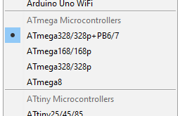
Works… kindof.
The following works:
|
1 2 3 4 5 6 7 8 9 10 11 12 13 14 15 16 17 18 19 20 21 22 23 24 25 26 27 |
#define DigitalPinA 14 // PB6 #define DigitalPinB 15 // PB7 #define DigitalPinC 16 // same pin as A0 #define AnalogPin A1 [...] void setup() { // put your setup code here, to run once: pinMode (DigitalPinA, INPUT); pinMode (DigitalPinB, INPUT); pinMode (DigitalPinC, INPUT); } void loop() { // put your main code here, to run repeatedly: SomeVarA = digitalRead(DigitalPinA); SomeVarB = digitalRead(DigitalPinB); SomeVarC = digitalRead(DigitalPinC); SomeVarAnalog = analaogRead(AnalogPin); [...] } |
While the following does not work:
|
1 2 3 4 5 6 7 8 9 10 11 12 13 14 15 16 17 18 19 20 21 22 23 24 25 26 27 |
#define DigitalPinA 14 // PB6 #define DigitalPinB 15 // PB7 #define DigitalPinC A0 // should be the same pin as 16 #define AnalogPin A1 [...] void setup() { // put your setup code here, to run once: pinMode (DigitalPinA, INPUT); pinMode (DigitalPinB, INPUT); pinMode (DigitalPinC, INPUT); } void loop() { // put your main code here, to run repeatedly: SomeVarA = digitalRead(DigitalPinA); SomeVarB = digitalRead(DigitalPinB); SomeVarC = digitalRead(DigitalPinC); SomeVarAnalog = analaogRead(AnalogPin); [...] } |
When I try to access a pin digitally by its analog reference (A0 in the example above), it does not work. Initially I changed pins_arduino.h with regard to the analog pin references (which originally started at 14):
|
1 2 3 4 5 6 7 8 |
#define PIN_A0 (16) #define PIN_A1 (17) #define PIN_A2 (18) #define PIN_A3 (19) #define PIN_A4 (20) #define PIN_A5 (21) #define PIN_A6 (22) #define PIN_A7 (23) |
This seemed to be logical to me, but this did not work either: The analog references were not working for analogRead! I can’t work out what I do wrong – so if anyone has an idea, please leave a comment. For the time being just remeber to use the numeric references when using digital I/O, and the Ax references for analog inputs.
Update Stability
Modifying boards.txt as given above may not be stable with regard to updates – make sure you have a copy somewhere. At some point I’ll need to find out how to implement my additions properly, following the standards.
Final Remarks
I only needed ATmega328, but following the above scheme, ATmega8 and ATmega168 should work the same way.
I’ll reach out to the community – perhaps someone with more insights can clear up my confusion with regard to the analog pin reference. And perhaps carlosefr will add the pins to his board definitions.
change for use I2C
#define PIN_WIRE_SDA (18)
#define PIN_WIRE_SCL (19)
to
#define PIN_WIRE_SDA (20)
#define PIN_WIRE_SCL (21)
Thanks for pointing this out! Still, I’d really recommend to use MiniCore.
Wow!…
Minicore does nothing for me. Just ditch the arduino bloatware:
An error occurred while uploading the sketch
avrdude: can’t open device “giveio”
avrdude: failed to open parallel port “lpt1”
Hi Chaservice,
I suppose you’re using Windows 10. Under Windows 10 the driver model has significantly changed, and I never got my parallel programmer working again. There are pages on the net that claim that it should work, like e.g. this one, but I never got it working – but I only tried with Bascom, which is a problem in itself. A while ago I bought an USB programmer, and since then my urge to fix this has died away. Another pitfall: You’ll need 64 bit giveio for 64 bit Windows.
Would be glad to here if and how you fixed it in the end.
– Hauke