Title Image Project: LED Controller
To create a lamp with adjustable color temperature and brightness, I use a warm/cold white dual LED strip, an ATtiny45 MCU with N-channel MOSFETs and two adjustable resistors. This article contains the hardware and software setup. The title image of this blog shows the project.
The first part of this blog post is mainly bla bla about the why and how I arrived at the final solution – click here to skip to the final solution.
Preface
To start with blogging projects, I picked the project shown in the title image. It certainly is not a very innovative project – you’ll find similar stuff all over the internet – but, well, I need some practice with the blog and all, so why not start simple?
So let’s start with the electronics for my
Color-adjustable, dimmable LED ceiling lamp
My girlfriend and I cannot find a nice ceiling lamp for our sofa niche, so we decided to build our own. It will be made from wood, shaped like a turned up boat, and the inner side will be plated with gold leaf. It’s not ready yet, so I can’t show any pictures. What we did so far is buying two boards of plywood, just 2 mm thick, and bent them using hot steam. That actually went very well already on the first try – we fixed the boards in the desired shape, heated water in two big pots and put the wood into the hot steam. We covered it with plastic shopping bags, and after 20-30 minutes of steaming the wood kept the desired form. Nice!
The goal
Since the lamp is supposed to light a place that should be cosy, but may also need bright, clear light at times, I decided that I want a lamp where I can adjust color temperature between warm white and cold white, as well as adjust the general brightness.
First approach: RGB LEDs → failure!
At first, I thought I go for RGB LED strips (aka. “Neopixels”), but this turned out to be stupid: You cannot get decent white light from these. The red, green and blue colors are far too narrow banded, not really covering the whole spectrum. If you look on e.g. a printed book cover (which uses CYMK-colors), the colors may look very strange in RGB LED “white” light.
Side remark: Now I have lying around a Neopixel LED strip – which brought me to the idea for another project, but this will be the topic of later posts.
Second approach: Dedicated cold/warm LEDs → much better.
So I bought this LED strip set. It has 150 cm of dual LED strip: There are warm white and cold white LEDs in it. Since these use some flourescent stuff to create white light from a blue or ultraviolet LED, they are broad spectrum and thus create nice light.
")
")
The set comes with a controller and an IR remote that allows in principle exactly what I want: Adjust the color temperature, and dim the lamp. But…
- I do not like having another remote lying around.
- I do not think that my sofa niche lamp should need a battery (that of the remote).
- The implementation is crappy: The adjustment steps are coarse (only eight brightness steps).
- The priority is on equi-brightness – when I sweep from warm white to cold white, the general brightness keeps the same. The reasoning behind it is clear and sound, but as a result, the LED strip is powered at a maximum of 50%. So I do not get the full possible brightness.
Solution: Build my own LED controller
General design
I use the warm/cold dual LED strip from the purchased set, also the power supply (which is capable of driving up to 300 cm of the same strip, so if I drive all LEDs of 150 cm at full power, I’m well within specification), but create my own LED controller. This is…
- using variable resistors to adjust brightness and color.
- based on an ATtiny45 microcontroller (MCU). This is cheap, has builtin AD converters, and has two hardware PWM outputs.
- using N-channel MOS FETs as LED drivers.
Parts list
| 1 | ATtiny45 | Conrad 4.- € |
Used the DIL 8 package – makes soldering on stripboard easy |
| 1 | DIL 8 socket | Conrad 0.15 € |
Need to be able to remove the MCU for reprogramming (Alternative: build in a socket for in-circuit programming) |
| 2 | 100 Ω resistor | < 0.10 € | From a set of resitors, which loweres the price for one down to 0.01 € |
| 2 | 1 kΩ resistor | < 0.10 € | dito |
| 2 | 10 kΩ variable resistor | 0.70 € | Did use linear potentiometers with 6 mm axis (not trimming poti’s) and added nice and elegant turning knobs – these were about 2.- € each |
| 2 | IRLB8721 N-channel MOS FET | Conrad 0.60 € |
Capable of driving > 60 A and has very low D-S resistance (Datasheet)- way beyond what I need. They don’t even get slightly warm in opration. |
| 1 | LED strip set | Conrad 60.- € |
Includes power supply (capable of driving 300 cm of LED strip), 150 mm of cold/warm dual LED strip (brightness equivalent to roughly a 70-100 W incandecent bulb), the (not-used) controller and IR remote. It is likely that with looking a bit around you’ll find this cheaper. And you might even use the controller box: It basically contains the MOS FETs, a voltage controller and a microcontroller (cannot tell which). If you do a little reverse engineering, you may just get away with the ATtiny45 and two variable resitors – or even use the remote and do a good implementation. |
| 1 | DC/DC converter module 24V → 5V |
Watterott 2.50 € |
For 2.50 € I get an adjustable DC/DC buck converter with about 90% efficency – I did not even bother to think if I could build a different power source for the ATtiny. |
| 1 | Stripboard | 1.- € | I wanted it to be long and narrow (10 × 40 wholes). |
| Mounting material | 10.- € | Some clamps for the cable, screws, housing | |
| # | Part | Source* Price each (ca.) |
Remarks |
*Please note: I do not get any money from the distributors I mention here! The only reason I state the source is to help readers to acquire the parts if they have difficulty finding them. Most of the parts are available from plenty of distributors, and the ones I picked are usually not even the cheapest, but the most convenient for me. Especially Conrad has a store nearby, which is why I buy many parts there, despite the comparatively high prices.
If I do not state a source, I had the item lying around. You’ll get these things usually from any electronics distributor.
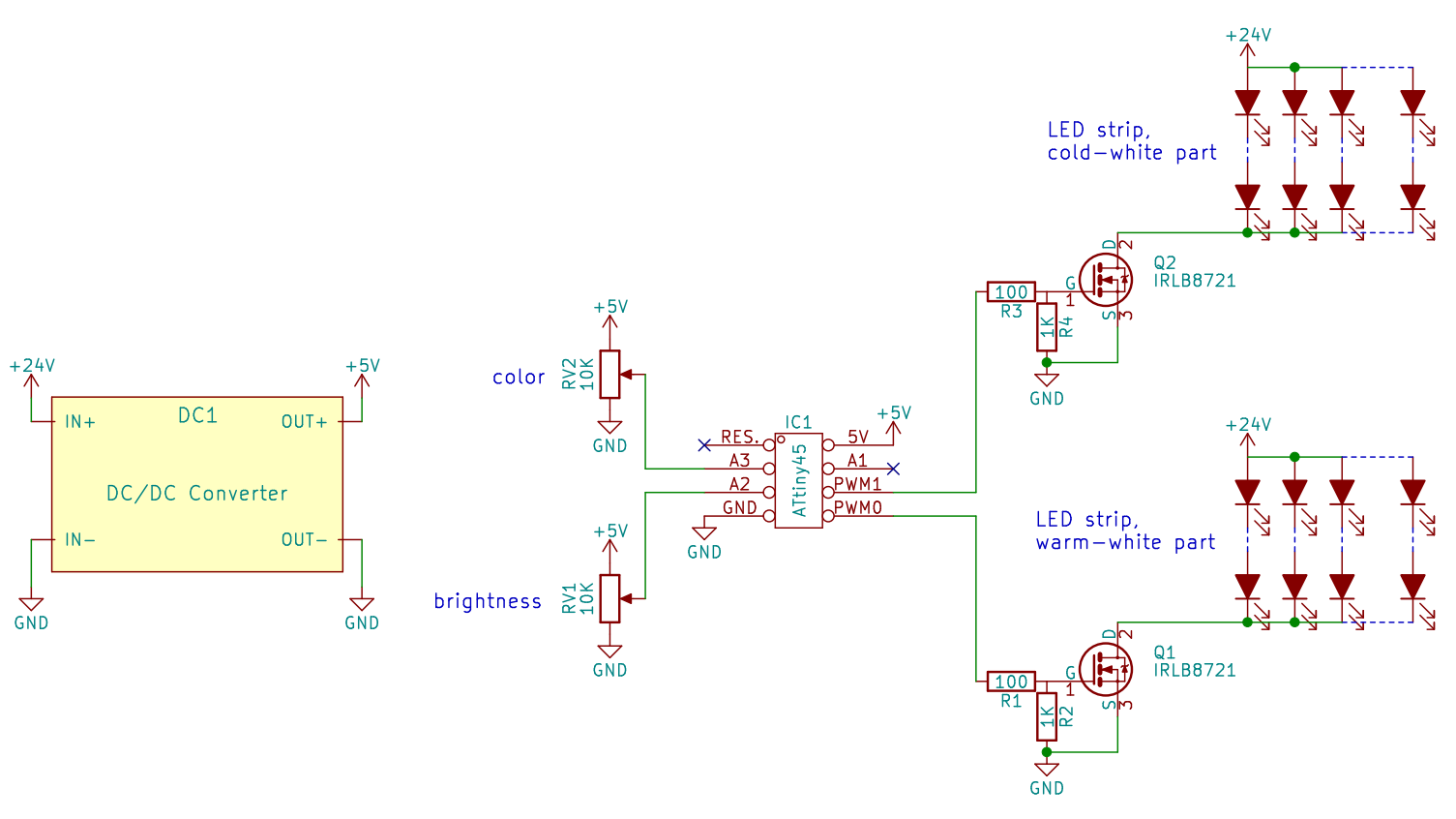
The circuit
The DC/DC converter takes the 24V from the power supply and provides 5V for the ATtiny. Be sure to adjust it to 5V before attaching the MCU.
The variable resistors are connected between 0V and 5V, so that the center pin will provide any voltage between these, dependent on knob position. I use linear resistors – any non-linear behaviour might in the end also be done by software. The center pin of the variable resistor is connected to one of the ADCs of the microcontroller, so that the knob position can be measured.
The brightness of the LEDs is controlled by pulse-width modulation (PWM). The ATtiny45 offers two hardware PWM outputs, which is really nice, since it takes away the need to implement software PWM, which always is tricky due to the tight timing requirements. It is capable of 8 bit PWM, so I have 256 bightness steps available for each warm and cold color LEDs. Setting the chip to 16 MHz speed, the PWM is of about 1 kHz, which means the light will not flicker.
The chip itself cannot stand the required voltage and current necessary to drive the LEDs, which is where the N-channel MOS FET comes into play. It can switch the 24V current on and off quickly enough to translate the 5V low power PWM of the ATtiny into high power pulses. These are fed into the LED strip, and the LEDs will appear brighter or dimmer, based on the duty cycle of the PWM.
Here’s the circuit diagram (click for larger view):
The software
The ATtiny can be programmed very well with the Arduino IDE. You need to import a board library – I use this one by David A. Mellis. My source code features…
- reading the variable resitors and averaging (median) 17 measurements in order to minimize flicker from jumping least significant bit.
- soft start feature: When switched on, the lamp will increase brightness “slowly” (i.e. within 1-2 sec) from 0 to the currently set brightness.
- calculating the PWM values for the cold and warm LEDs. I do not aim for keeping brightness constant when changing color temperature. My algorithm is:
- Get maximum brightness from variable resitor 1
- Get color temperature fom variable resistor 2
- for color resistor set between 0..50%, set…
- warm LED to maximum brightness
- cold LED linearly between 0..100% of maximum brightness
- for color resistor set between 50..100%, set…
- warm LED linearly between 100..0% of maximum brightness
- cold LED to maximum brightness
- for color resistor set between 0..50%, set…

As a result, at 50% color setting and 100% brightness setting, both LED colors are at full brightness, allowing me to get as much light as possible from the strip.
Source code
Please note: Set the fuses so that the microcontroller runs at least at 8 MHz, better even 16 MHz (PLL oscillator). This is to avoid any flicker from PWM. The internal oscillator of the ATtiny is sufficient, no need for an external one.
If you think 17 averaging values are wrong, adjust the line
|
1 |
#define AveragingReadouts 17 |
to meet your preference.
Source code is free for anyone to use and modify.
|
1 2 3 4 5 6 7 8 9 10 11 12 13 14 15 16 17 18 19 20 21 22 23 24 25 26 27 28 29 30 31 32 33 34 35 36 37 38 39 40 41 42 43 44 45 46 47 48 49 50 51 52 53 54 55 56 57 58 59 60 61 62 63 64 65 66 67 68 69 70 71 72 73 74 75 76 77 78 79 80 81 82 83 84 85 86 87 88 89 90 91 92 93 94 95 96 97 98 99 |
#include <stdlib.h> #include <avr/pgmspace.h> #define WarmLEDPin 0 #define ColdLEDPin 1 #define BrightnessPotPin A2 #define ColorPotPin A3 #define AveragingReadouts 17 unsigned int BrightnessReadout[AveragingReadouts]; unsigned int ColorReadout[AveragingReadouts]; unsigned int BrightnessCopy[AveragingReadouts]; unsigned int ColorCopy[AveragingReadouts]; long Brightness = 0; long CurrentColor = 0; long LastBrightness = 0; long LastColor = 0; long WarmPart; long ColdPart; long WarmCalc; long ColdCalc; uint8_t MedianIndex; uint8_t ReadoutPointer = 0; uint8_t ReadoutCounter; boolean SoftOnDone = false; void setup() { // put your setup code here, to run once: noInterrupts(); pinMode(WarmLEDPin, OUTPUT); pinMode(ColdLEDPin, OUTPUT); pinMode(BrightnessPotPin, INPUT); pinMode(ColorPotPin, INPUT); analogWrite(WarmLEDPin, 0); analogWrite(ColdLEDPin, 0); MedianIndex = AveragingReadouts / 2; } void loop() { // put your main code here, to run repeatedly: BrightnessReadout[ReadoutPointer] = analogRead(BrightnessPotPin); ColorReadout[ReadoutPointer] = analogRead(ColorPotPin); ReadoutPointer++; if (ReadoutPointer == AveragingReadouts) { ReadoutPointer = 0; } // get median by sorting array and getting middle element for (ReadoutCounter = 0; ReadoutCounter < AveragingReadouts; ReadoutCounter++) { BrightnessCopy[ReadoutCounter] = BrightnessReadout[ReadoutCounter]; ColorCopy[ReadoutCounter] = ColorReadout[ReadoutCounter]; } sort (BrightnessCopy, AveragingReadouts); sort (ColorCopy, AveragingReadouts); CurrentColor = ColorCopy[MedianIndex]; if (SoftOnDone) { Brightness = BrightnessCopy[MedianIndex]; } else { delay (10); Brightness++; SoftOnDone = (Brightness >= BrightnessReadout[0]); } if ((Brightness != LastBrightness) || (LastColor != CurrentColor)) { LastBrightness = Brightness; LastColor = CurrentColor; WarmPart = min(CurrentColor, 511); // 0..1023 --> 0..511..511 ColdPart = 511 - max((CurrentColor - 512), 0); // 0..1023 --> 511..511..0 WarmPart *= Brightness; ColdPart *= Brightness; WarmCalc = min(WarmPart / 2050, 255); // 2050 = 1023 * 511 / 255 ColdCalc = min(ColdPart / 2050, 255); analogWrite(WarmLEDPin, byte(WarmCalc)); analogWrite(ColdLEDPin, byte(ColdCalc)); } } void sort(int a[], int size) { for(int i=0; i<(size-1); i++) { for(int o=0; o<(size-(i+1)); o++) { if(a[o] > a[o+1]) { int t = a[o]; a[o] = a[o+1]; a[o+1] = t; } } } } |
The sort algorithm I have “stolen” from this page – thanks a lot Steve for sharing this!
Final remarks
To build all this yourself, you of course need a programmer for the ATtiny microcontroller. There are zillions around for less then 30.- €. I personally use this very simple parallel port programmer (sorry, link is German). This came at practically no cost since I had all parts lying around from old electronics. If you have to buy them, you’ll end up at about 10.- € – not worth the trouble: Buy a modern USB programmer instead. It will save you the need to find a computer with parallel port. Be aware that even that might not be sufficient – Windows 10 introduces a new driver scheme that spoils many software trying to access the parallel port directly.
There are two pins still unused on the ATtiny – you may even implement a switch that changes to equi-brightness mode or something…
As stated above, I built this on stripboard, which is my favorite “platform”. I currently lack the tools to etch my own PCBs, but I fare quite well without.
The circuit diagram was done using KiCad – thanks a lot to the community for this nice piece of software!